Circuit Pack Descriptions
Issue 8.0 July 2002
7-63
General Description of Operation 7
The IS3 (1.3 STD) circuit pack terminates one bidirectional IS-3 line. In the
transmit direction (toward the OC-48 line), the IS3 (1.3 STD) circuit pack converts
the incoming IS-3 optical signal to an electrical STS-3/3c signal (155.52 Mb/s).
The STS-3/3c signal is demultiplexed into three STS-1 signals (51.84 Mb/s) and
synchronized to the system clock. The three STS-1 signals are then multiplexed
back to one STS-3/3c signal and sent to an OC48 Transmitter (OC48 TRMTR)
circuit pack. In the receive direction (toward the IS-3 line), the IS3 (1.3 STD) circuit
pack accepts one STS-3/3c signal from an OC48 Receiver (OC48 RCVR) circuit
pack and demultiplexes it to three STS-1 signals. The three STS-1 signals are
synchronized to the system clock, multiplexed back to one STS-3/3c signal, and
converted to an optical IS-3 signal for transmission. The IS3 (1.3 STD) circuit pack
also interfaces with the Line Controller (LNCTL) circuit pack for that particular
OC-48 high speed line.
Detailed Description of Operation 7
Transmission Circuitry 7
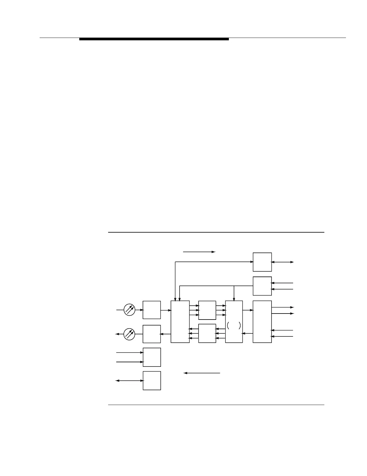
Transmit Direction. 7Figure 7-21 provides an overall block diagram of the IS3 (1.3
STD) circuit pack.
Figure 7-21. IS3 (1.3 STD) Circuit Pack Block Diagram
Receive Direction
Transmit Direction
BCLAN
-48V (B)
-48V (A)
System Clock
Transmit
Pointer
Processor
Recieve
Pointer
Processor
Electrical
to
Optical
Module
Power
Circuit
Board
Controller
Circuit
Optical
to
Electrical
Module
IS-3
IS-3
STS-3
Byte
Processor
(IS-3 Line)
STS-3
Byte
Processor
Low
Speed
SONET Overhead
TOH
Processor
HS
Intfc
Timing
Intfc
From OC48
RCVRs
To OC48
TRMTRs
From TG3
(DS1)s
To/From
TOHCTL