Power
4-6 Issue 8.0 July 2002
Power Dissipation 4
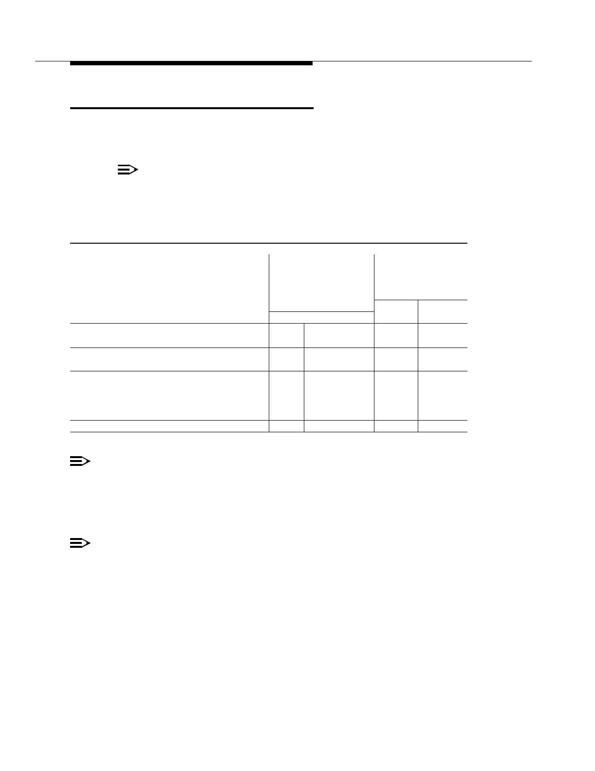
Table 4-1 shows the maximum power dissipation and current drains for the
FT-2000 OC-48 Lightwave System.
NOTE:
Refer to the Floor Plan Data Sheet (FPD 804-911-168-[ ]) for complete
information on power engineering for the FT-2000 OC-48 Lightwave
System.
NOTE:
Nominal (List 1) current drains are used to size batteries and rectifiers. To size
batteries and rectifiers, use twice the nominal current drain per feeder. These current
drains represent the average busy-hour current at normal operating voltages. Nominal
current drains occur at −48 V.
NOTE:
Maximum (List 2) current drains are used to size each feeder cable and fuse. To size
feeder cables and fuses, use the maximum current drain per feeder. These current
drains represent the peak current under worst-case operating conditions. Normally, the
current for the system is shared equally by both feeders. If one feeder fails, the other
feeder carries the total load for both feeders (feeder A + feeder B current). Maximum
current drains occur at −42.75 V.
Table 4-1. Power Dissipation and Current Drains
Current Drain (Amps)
Maximum per Feeder
Power
(Two Feeders
Required)
Dissipated Nominal Maximum
Equipment Package (Watts) (Watts/ft
2
) (Note 1) (Note 2)
FT-2000 OC-48 Add/Drop-Rings (E-Bay)
487 69 5.1 11.4
Terminal for two-Fiber Rings
FT-2000 OC-48 Add/Drop-Rings (D-Bay) 1142 162 11.0 26.7
Terminal for two two-Fiber Rings
FT-2000 OC-48 Repeater Bay with
— One Repeater Shelf — System Controller
— Two Repeater Shelf — System Controllers
— Three Repeater Shelf — System Controllers
175
350
525
25
50
75
1.8
3.6
5.5
4.1
8.2
12.3
FT-2000 OC-48 Repeater Shelf 175 25 1.8 4.1