Circuit Pack Descriptions
7-44 Issue 8.0 July 2002
STS1E (LAA4) Circuit Pack Description 7
Purpose of Circuit 7
The STS-1 Electrical Interface (STS1E) circuit pack provides a low speed
interface between three synchronous EC-1 signals and an internal synchronous
155.52 Mb/s signal. The STS1E circuit pack is compatible with Release
4.0.0-ADR and later software.
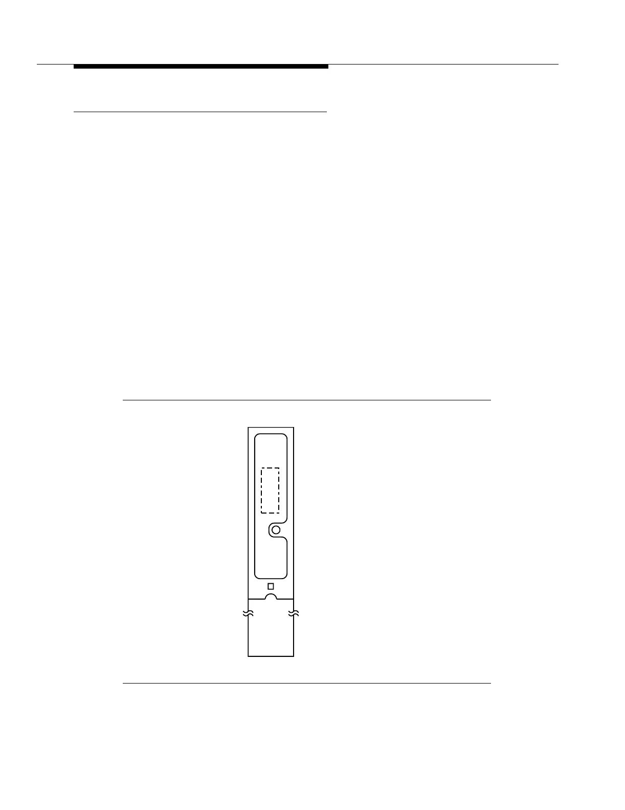
Faceplate LED 7
The STS1E circuit pack has a red FAULT LED on its faceplate (Figure 7-15). The
red FAULT LED is continuously lighted when a circuit pack failure is detected or
when the circuit pack loses power. If the circuit pack loses power, a separate path
is provided for power from the Line Controller (LNCTL) circuit pack to light the
FAULT LED on the STS1E circuit pack.
The board controller on the STS1E circuit pack detects hardware and software
faults on the circuit pack. When a fault occurs, the FAULT LED on the circuit pack
is continuously lighted. If an incoming EC-1 signal from the STSX-1 panel (or
equivalent) fails, the FAULT LED will flash on and off.
Figure 7-15. STS1E (LAA4) Circuit Pack
FAULT
xxxxxxxxx_
LAA4
STS1E