Platform Descriptions
Issue 8.0 July 2002
3-41
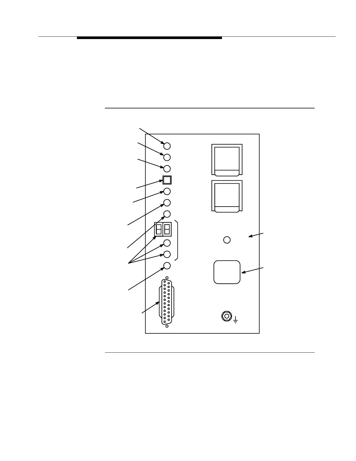
The user panel provides −48 V power filters, a PWR ON LED, an electrostatic
discharge jack, and system level information. Figure 3-22 shows the user panel
for the miscellaneously mounted FT-2000 OC-48 Repeater Shelf. Figure 3-7
shows the user panel for the FT-2000 OC-48 Repeater Bay except the line
identification label is the same as shown in Figure 3-22. For more information
about the user panel, refer to Volume I, Section 6, "Operations Interfaces."
Figure 3-22. User Panel (FT-2000 OC-48 Repeater Shelf) for
Miscellaneous Mounting Only
ACTY
ACTY
ABN
ACO/
LOCTR
-48A
10A,
60V
10A,
60V
-48B
FUSE
FUSE
LIFT UP
LIFT UP
USE
CIT
Line
Locator
Use CIT
CIT
(DCE)
STRAP GROUND
W
CIT Connector
LINE
LOCTR
Near-End
Activity
Far-End
Activity
NE
FE
Abnormal
MN
ESD WRIST
Pushbutton
PWR
ON
MJ
Minor Alarm
E
Identification
Label
CR
Critical Alarm
Major Alarm
Line Locator
Line
LINE
Alarm Cutoff/
NO. = 1
LINE
NO. = P
-48 V Power On