Power
Issue 8.0 July 2002
4-3
The 8-gauge power feeder stubs (power feeder A and power feeder B) are
terminated at the bay power distribution and fuse panel. Within the power
distribution and fuse panel, the power feeders are routed with 10-gauge wire to six
10-amp fuses (red lamp is lighted when blown). Three fuses are for power feeder
A and three fuses are for power feeder B. The bottom shelf and the fan assembly
(if equipped) share the first pair of fuses. The second pair of fuses is assigned to
the middle shelf. The third pair of fuses is assigned to the top shelf.
The power feeders are cabled, using 14-gauge wire, from the fuses down the right
side of the bay (when viewed from the front) to the shelves and the fan assembly
(if equipped).
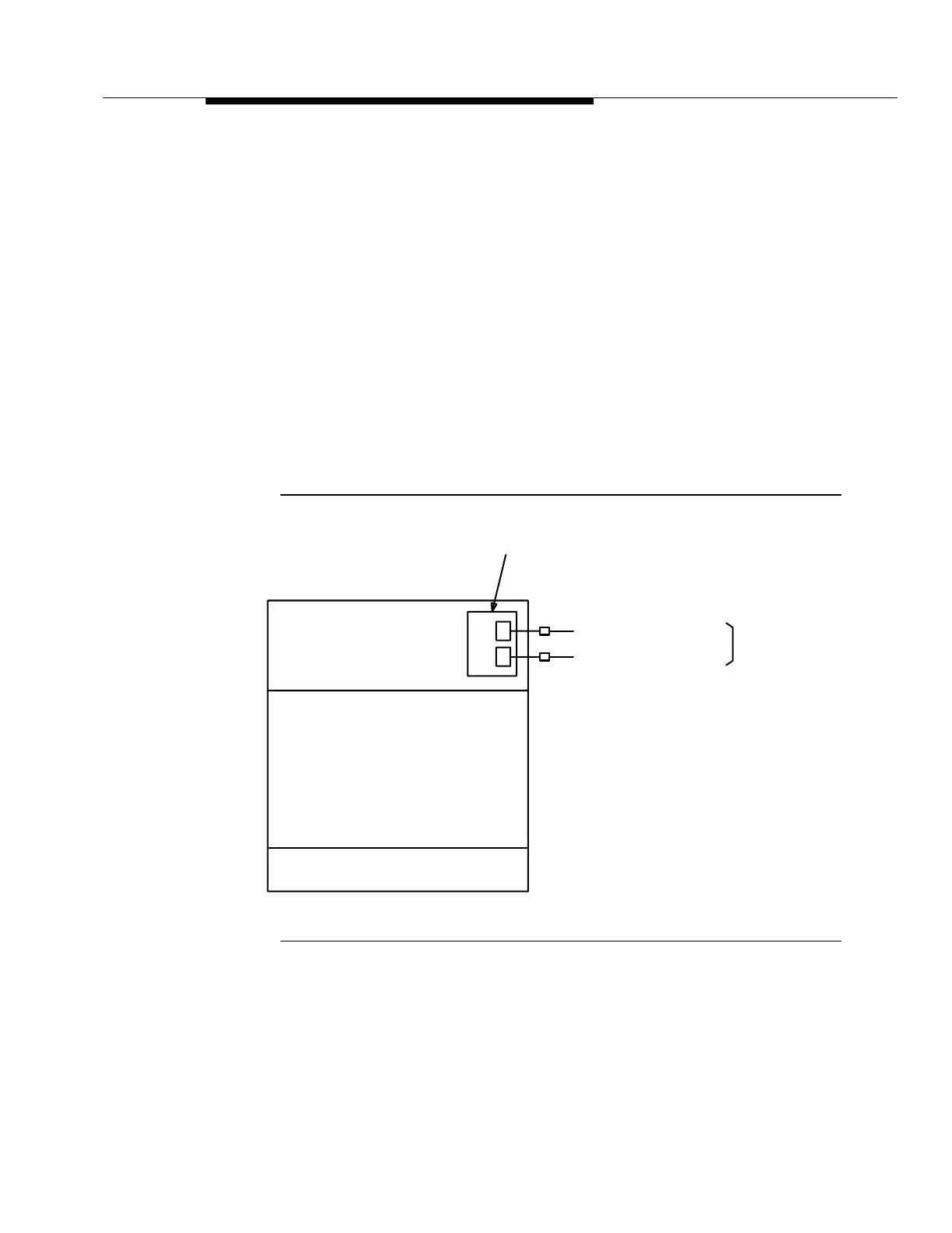
Figure 4-2 shows an example of how power is distributed to a miscellaneously
mounted FT-2000 OC-48 Repeater Shelf. The 8-gauge power feeder stubs are
terminated at two 10-gauge power connectors that are connected to the user
panel. The user panel is equipped with two 10-amp fuses: one fuse for power
feeder A and one fuse for power feeder B (red lamp is lighted when blown).
Figure 4-2. Miscellaneously-Mounted FT-2000 OC-48
Repeater Shelf Power Distribution
PC Tray
Battery
Office
To -48 V DC
User Panel
A
Power Feeder B and Return
Power Feeder A and Return
B