365-575-102 Detailed Level Procedure: DLP-541
Issue 8.0, July 2002 Page 3 of 4
18. DO NOT RESET the DRI switch at node P at this time. At FT-2000 primary
node P' (P prime), execute a manual DRI switch for each path being tested.
Use the FAULT-Switch-Path-STS3-Manual command for the appropriate
line(s) and tributary(s).
19. Repeat Steps 13 through 15 for each path being tested.
20. At the FT-2000 primary node P, reset the manual DRI switch for each path
being tested. Use the FAULT-Switch-Path-STS3- Reset command for
the appropriate line(s) and tributary(s).
21. Repeat Steps 13 through 15 for each path being tested.
22. At the FT-2000 primary node P', reset the manual DRI switch for each path
being tested. Use the FAULT-Switch-Path-STS3-Reset command for the
appropriate line(s) and tributary(s).
23. Verify that there are no alarm or status conditions in the ring.
24. This completes testing path integrity (Figure 2).
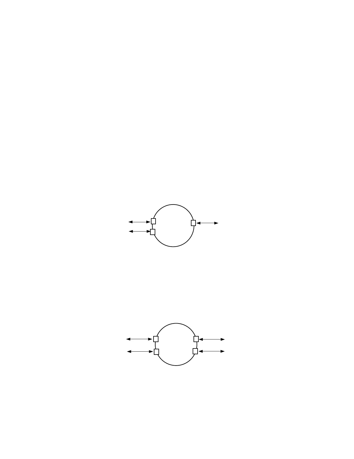
Figure 1 – Testing Local FT-2000 Ring (Three Nodes)
Figure 2 – Testing Local FT-2000 Ring (Four Nodes)
Local
FT-2000
Ring
Test Set
S
P
Note: One DRI cross-connection to the outside. Both DRI cross-connections and local
source/destination cross-connections terminate directly to test sets.
Test Set
Test Set
Local
FT-2000
Ring
Test Set
S
P
Note: Two DRI cross-connections to the outside. Both DRI cross-connections terminate
directly to test sets.
P'
S'
Test Set
Test Set
Test Set