EasyManuals Logo

Parker Compax3 Fluid T40 User Manual

Parker Compax3 Fluid T40
470 pages
To Next Page IconTo Next Page
To Previous Page IconTo Previous Page
Page #106 background imageLoading...
Page #106 background image
Setting up Compax3 C3F_T40
106 192-121102 N04 June 2008
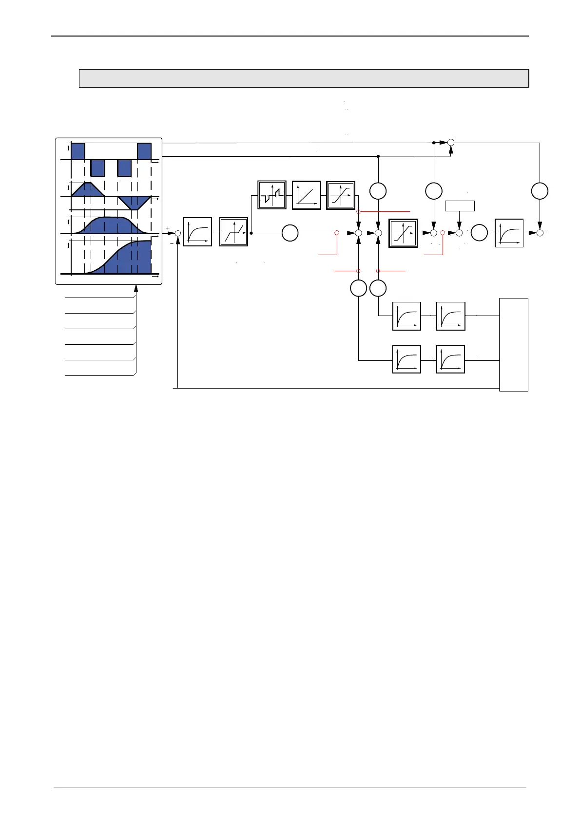
4.3.3.4 Controller strucutre auxiliary axis
Actual value
monitoring
Setpoint generator
2101.14
2101.13
2260.22
2260.21
2050.9
2050.24
a
v
697.12
2101.11
2270.8
2260.14/.15 2260.16/.17
2101.42101.7
2101.8 2101.5
2260.20
Setpoint position
Speed
Acceleration
Deceleration
Acceleration jerk
Deceleration jerk
697.13
697.11
697.15
697.14
+
+
-
+
+
-
+
+
K
P
K
v
K
vv
K
va
2050.8
K
a
+
+
K
SG
.14
.15
+
+
+
+
K
uv
t
s
v
t
a
t
r
t
Measurement values: Status objects are displayed in red.
Fctors and time
constants
Corresponding objects are displayed in blue.
Below you can find the descriptions of the individual objects.

Table of Contents

Questions and Answers:

Question and Answer IconNeed help?

Do you have a question about the Parker Compax3 Fluid T40 and is the answer not in the manual?

Parker Compax3 Fluid T40 Specifications

General IconGeneral
SeriesCompax3
Power Supply Voltage24 VDC
Output Current40A
Protection ClassIP20
CommunicationCANopen, RS232
Operating Temperature0°C to +45°C
Relative Humidity5 to 95 %, non-condensing
Storage Temperature-25 to +70 °C

Related product manuals