Parker EME
Motion control
192-121102 N04 June 2008 177
5.5.2. Procedure when working with the C3_getSystemFingerPrint
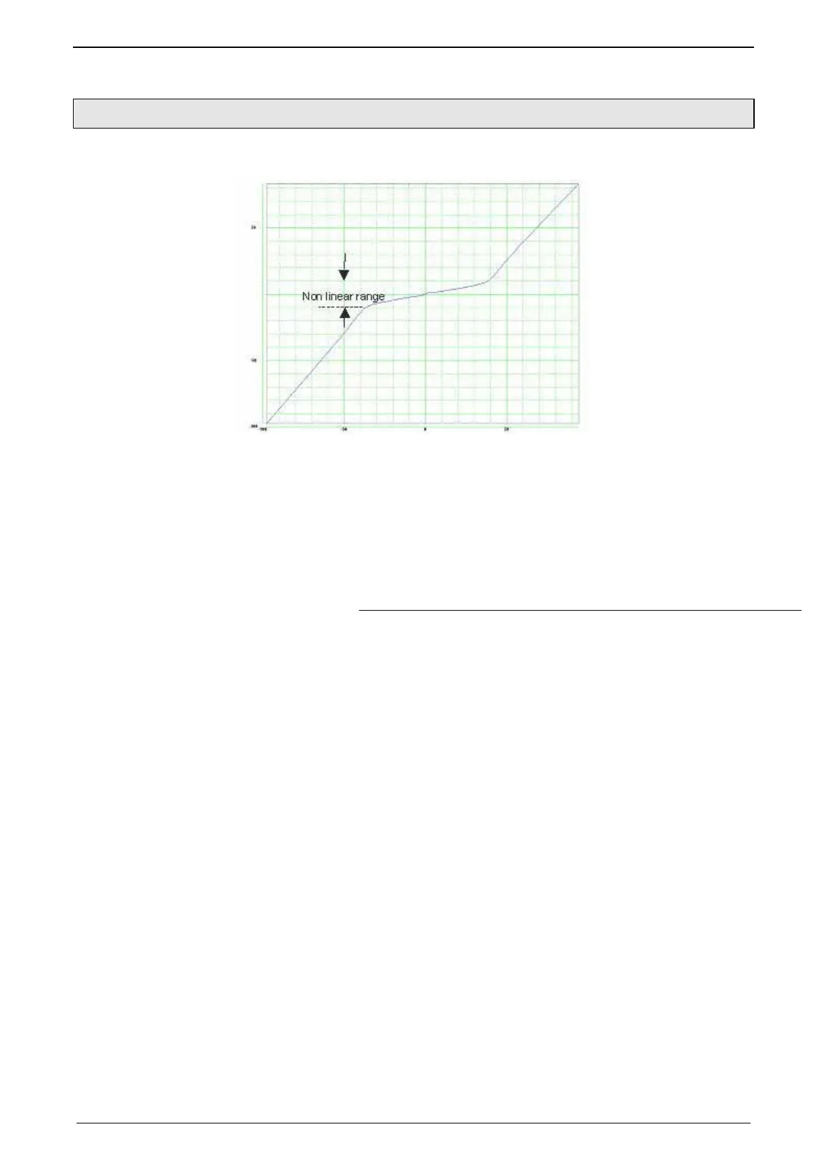
Example of a valve characteristic line (volume current via control signal):
Procedure:
Specification of the travel range available for the measurement with min_Position
and max_Position.
Setting max_Velocity (is valid symmetrically for positive and negative values).
With max_Velocity, you make 2 settings at once: the max. velocity during the
measurement and the measurement range.
Connection between velocity (max_Velocity) and the relative volume current:
%100_
___[%]__
max_
⋅
=
surfaceACylinder
currentvolumenominalValvecurrentvolumerelative
Velocity
(Value_nominal_volume_current Valve-nominal-volume-current;
Cylinder_surfaceA: Cylinder_surface-A
max_Velocity should be set at least so high that the measurement exceeds the
non-linear range shown above, as the characteristic line is continued at the same
slope outside the measured velocity range.
the Number_of_Measuring_Points should be set high enough so that the non-
linearity to be emulated can be exactly detected (typically N=100).
Start of the measurement by positive edge at the Execute input.
The state of the measurement can be monitored via the Status, Done, Error and
ErrorID outputs.
A positive edge at the Done output shows the successful termination of the
identification:
Measurement terminated successfully
The characteristic line was inverted and written into the FLASH memory.
In the conditioning chain responsible for the measured system, the curve ID
was already set to the new characteristic line and the characteristic line
compensation was activated.

 Loading...


