Parker EME
Setting up Compax3
192-121102 N04 June 2008 49
4.1.5. Configuring drive2
The following dialogs can only be selected, if under "number of drives" 2 drives
were selected.
Drive2 is configured as described under drive1, the selection of the path
measurement system EnDat and Sine/Cosine is however not available for drive2.
Select operating mode (only applies for Compax3 T30 and T40; not for
Compax3 Ixx11)
The possible operating mode of the auxiliary axis depends on the operating mode
set for the main axis
Main axis operating mode Possible operating mode of the auxiliary
axis
Pressure/Force Controller Pressure/Force Controller
Positioning & Pressure/Force Controller Positioning & Pressure/Force Controller
or
Pressure/Force Controller
4.1.6. Sensors
Force or pressure sensors are req uired for the control of force or pressure.
Altogether 6 analog inputs are available for the integration of the pressure and
force sensors for the drives 1 and 2 (if no analog input is used as position feedback
system).
Inputs that are not utilized can be used in an IEC61131-3 program (for example as
setpoint input).
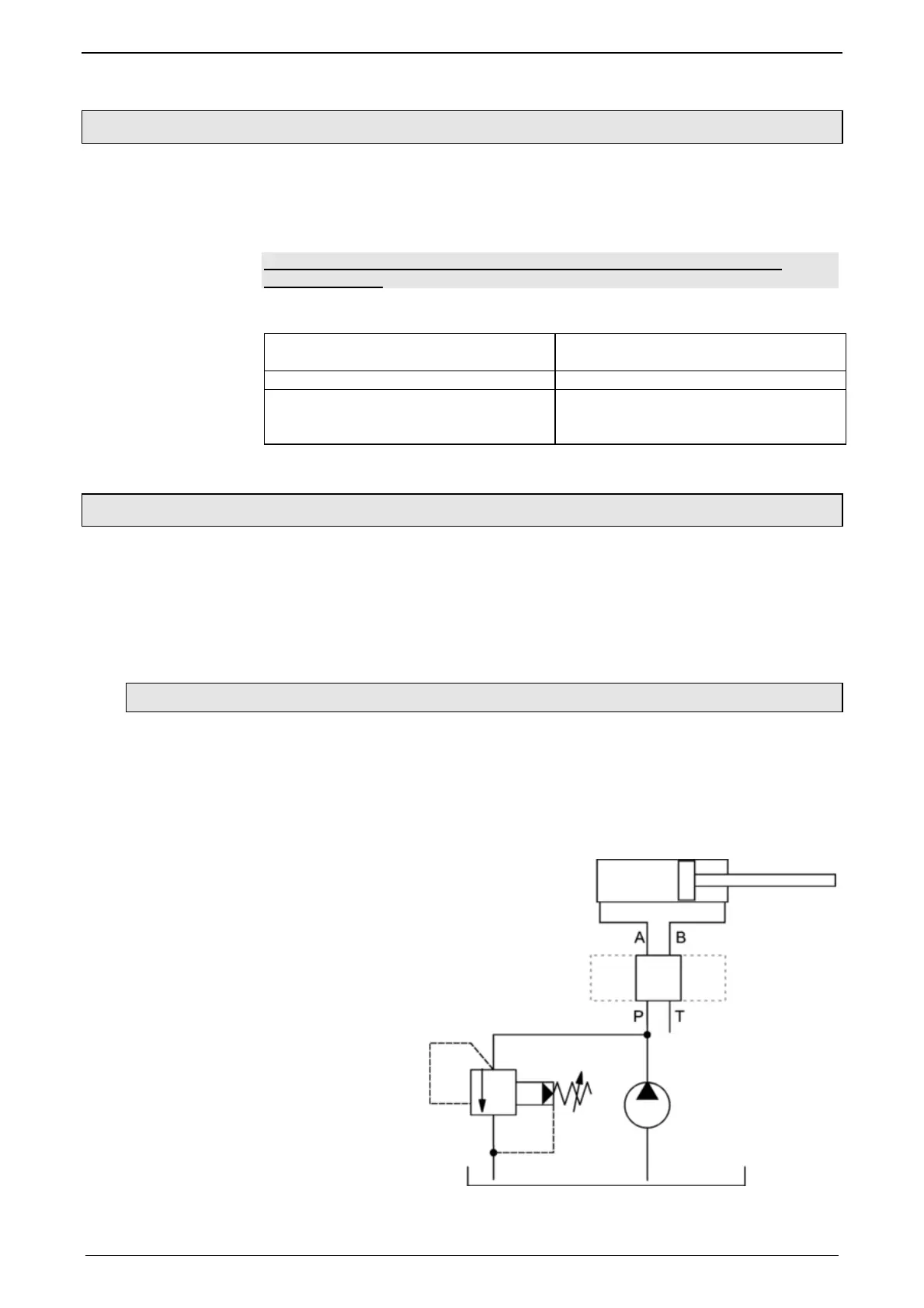
4.1.6.1 Pressure sensors
Pressure sensors can be used for the cnontrol of pressure or force (with pressure
P
A
& P
B
).
If pressure sensors are utilized for the control of force, the resulting force is
calculated via the the differential pressure P
A
- P
B
and the ratio of major area to
minor area of the cap
A maximum of 4 pressure sensors per axis can be parameterized. The logic
assignment of the sensors results from the following image.

 Loading...


