Parker EME
Motion control
192-121102 N04 June 2008 303
5.13 Process image
In this chapter you can read about:
Reading digital inputs (C3_Input) .....................................................................................303
Write digital outputs (C3_Output) .....................................................................................303
Reading/writing optional inputs/outputs............................................................................304
Memorizing the signals with the tri
gger event (C3_TouchProbe).....................................306
Integration of Parker I/Os (PIOs)......................................................................................309
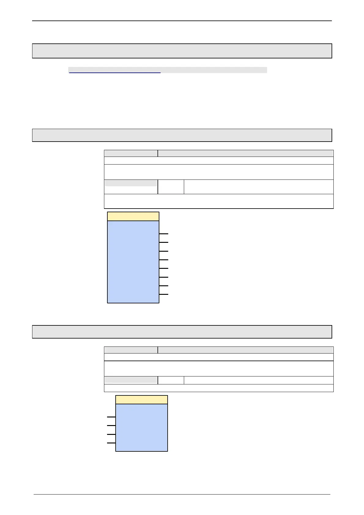
5.13.1. Reading digital inputs (C3_Input)
FB name C3_Input
Used to generate a process image of the digital inputs.
VAR_INPUT
I0 ... I7
BOOL
Displays the logic status of the respective input (with low
active inputs, the physical statuses are negated).
Notes: the module should always be brought up at the beginning of the processing
cycle.
I5: BOOL
I6: BOOL
I7: BOOL
C3_I nput
I1: BOOL
I2: BOOL
I3: BOOL
I0: BOOL
I4: BOOL
5.13.2. Write digital outputs (C3_Output)
FB name C3_Output
Used to generate a process image of the digital outputs.
VAR_OUTPUT
O0 ... O3
BOOL Displays the status of the respective output.
Notes: the module should always be brought up at the end of the processing cycle.
C3_O utput
O1: BOOL
O2: BOOL
O3: BOOL
O0: BOOL

 Loading...


