Parker EME
Setting up Compax3
192-121102 N04 June 2008 93
3: Set signal source with object name, number and if necessary unit
Define source: Draw the desired status object with the mouse (drag & drop) from
the "Status value" window (right at the bottom) into this area.
4: Set Channel offset to 0
5: Select channel display (GND, DC, AC, DIG)
DC: Display of the measurement values with constant component
AC: Display of the measurement values without constant component
DIG: Display of the individual bits of an INT signal source.
The displayed bits can be defined via the logic display mask.
GND: A straight line is drawn on the zero line.
6: Set Y-amplification (YDIV)
Change of the Y amplification YDIV in the stages 1,2,5 over all decades.
Arrow upwards increases YDIV, arrow downwards diminishes YDIV.
the standard value is 1 per DIV.
The measurement value of the channel at the cursor cross is displayed.
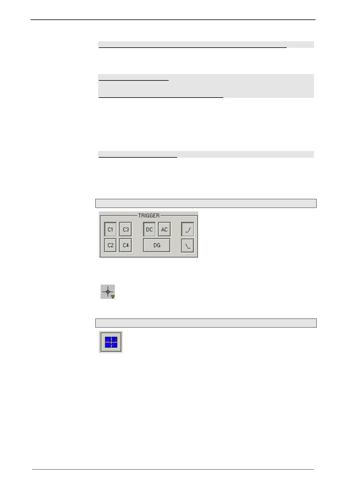
Trigger settings
Select trigger channel: Buttons C1, C2, C3, C4
Select trigger mode: DC, AC, DG
Select trigger edge: rising_/ or falling \_
the pretrigger as well as the trigger level are set by clicking on the trigger cursor
(
) directly in the OSCI display.
Special functions
Menu with special oscilloscope functions such as memorizing or loading settings.

 Loading...


