Parker EME
Setting up Compax3
192-121102 N04 June 2008 47
4.1.4. Configuring drive1
In this chapter you can read about:
Position feedback system drive1........................................................................................47
Cylinder / motor selection...................................................................................................48
Load configuration drive1 ...................................................................................................48
4.1.4.1 Position feedback system drive1
If the position feedback system is part of the cylinder / motor, it has already been
parameterized in the C3HydraulicsManager and this step is not needed.
Parameterizing a position feedback system:
General entries for each position feedback system:
Inversion of the direction: Inverts the sense of direction.
Rotatory position feedback system?
'EnDat (no further entries)
Sine cosine & RS422 encoder
Resolution in µm / bit
SSI:
Resolution in µm / bit
Update rate: Necessary updating time of the actual value in µs.
Word length: Gives the telegram length of the sensor.
Gray code: Sensor gray code coded yes/no.
Synchronous system: Sensor sends data synchronously to Compax3F step
yes/no
Baud rate/step: Max. transmission rate of the path measurement system.
Start-Stop:
Velocity of sound: Speed, at which the mechanical wave moves within the range
of the wave guide (e.g. 2830 m/s).
Update rate: Necessary updating time of the actual value in µs.
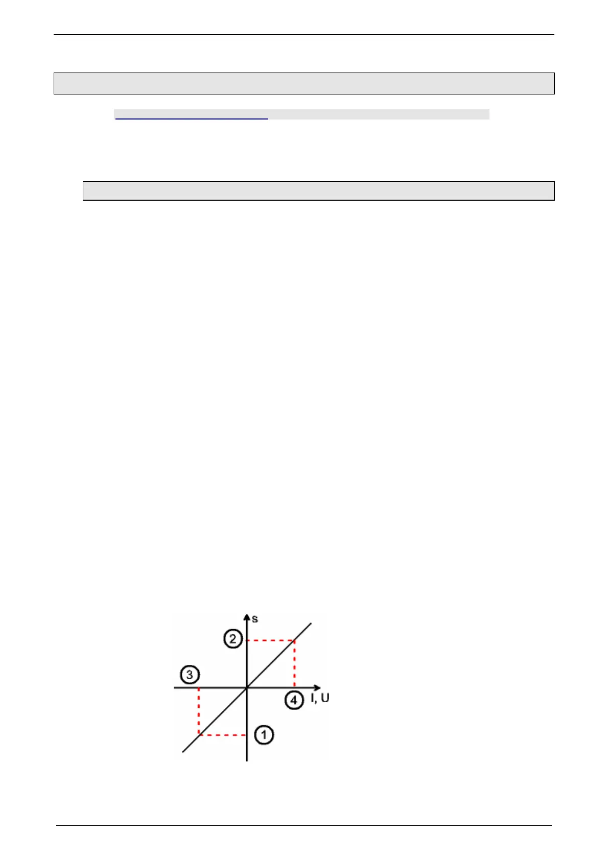
Analog:
Selection of the C3f analog interface
(2) - (1): Length path measurement system.
(3): Minimum signal of the path measurement system.
(4): Maximum signal of the path measurement system.

 Loading...


