Parker EME
Compax3F device description
192-121102 N04 June 2008 31
1. Feedback system / X13 High Density /Sub D
PIN RS422 Encoder SinusCosinus
1VSS
EnDat 2.1 Start / Stop
(Time of Flight)
SSI
1
+24V
max. 100mA
+24V
max. 100mA
2 Sense + Sense + Sense +
3
Sin + Sin +
4 Vcc +5V (controlled
on the encoder side)
Vcc +5V (controlled
on the encoder
side)
Vcc +5V (controlled
on the encoder side)
5 +5V (for encoder)
max. 150mA
+5V +5V
6 A-
Clock- INIT- Clock-
7 A+
Clock+ INIT+ Clock+
8 B+ COS+ COS+ STSP+
9
SIN- SIN-
10
11 Sense - Sense - Sense -
12 B- COS- COS- STSP-
13 N- N- DATA-
DATA-
14 N+ N+ DATA+
DATA+
15 GND GND GND GND GND
Max. start/stop time is 1.6ms (over 4.15m).
Note on F12:
+5V (Pin 4) is measured and controlled directly at the end of the line via Sense –
and Sense +.
Maximum cable length: 100m
Caution! Pin 4 and Pin 5 must under no circumstances be connected!
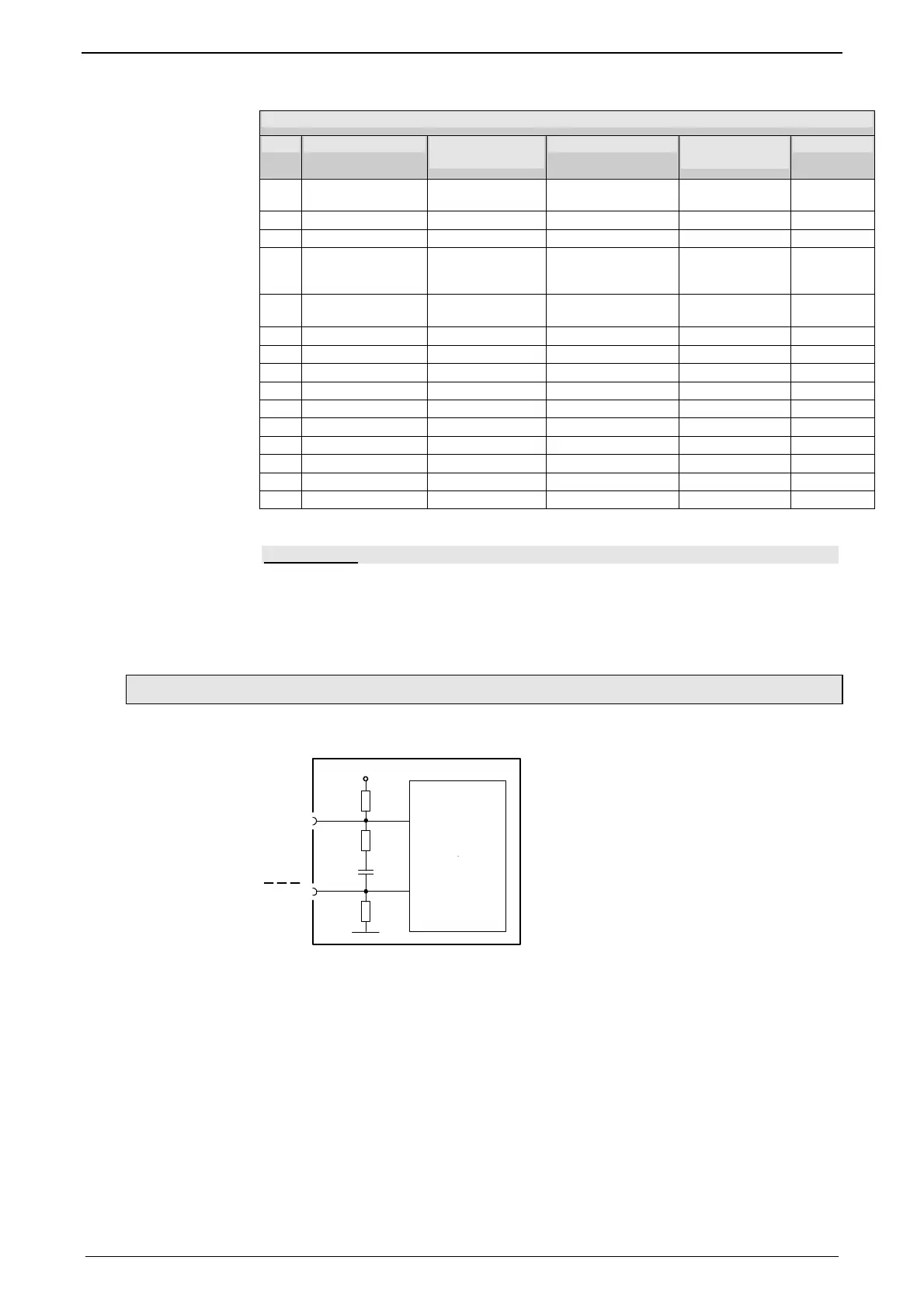
3.2.10.1 Connections of the encoder interface
10nF
+5V
121
Ω
1K
Ω
1K
Ω
GND
BN
RS422
Transceiver
BN
Compax3
The input connection is available in triple (for A & /A, B & /B, N & /N)

 Loading...


