Communication
C3F_T40
368 192-121102 N04 June 2008
C3 Master PIO
In the "C3 Master PIO" operating mode, the input window for the CANopen PIO
mapping is follwowing:
Please state, how many words the process image of the PIOs will need, 1.. 4
words are possible.
The process image is transmitted via teh process data objects as follows:
Digital Inputs: RPDO1
Analog Inputs: RPDO2
Digital Outputs: TPDO1
Analog Outputs: TPDO2
The inputs and outputs are stored in objects (O150.x ... O153.x).
Object 150.x: Digital Inputs
Object 151.x: Digital Outputs
Object 152.x: Analog Inputs
Object 153.x: Analog Outputs
The digital inputs and outputs can be read or written into in the IEC program via
modules (see page 309) in order to get an exact process image. Modules:
PIO_Input0_15, PIO_Input16_31, PIO_Input32_47, PIO_Input48_63,
PIO_Output0_15, PIO_Output16_31, PIO_Output32_47, PIO_Output48_63.
Before that, you must execute some initializations; this can be made with the aid of
the
PIO_INIT (see page 309) module.
6.5.1.2 Error reaction to a bus failure
Here you can adjust how Compax3 will respond to a fieldbus error:
Possible settings for the error reaction are:
No response
downramp / stop
Downramp / switch to currentless (standard setting)
6.5.1.3 Baud rate
Selecting the Baud rate.
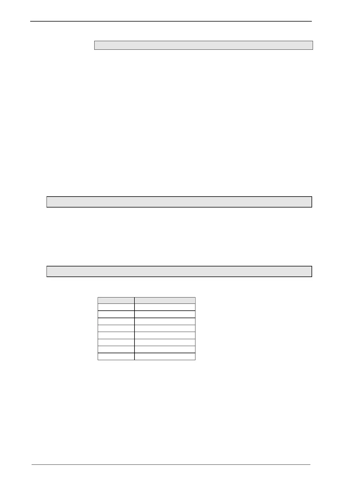
Bear in mind that the maximum cable length depends on the Baud rate:
Baud rate Maximum length
1Mbit/s 25m
800kbit/s 50m
500kbit/s 100m
250kbit/s 250m
125kbit/s 500m
100kbit/s 700m
50kbit/s 1,000m
20kbit/s 2,500m

 Loading...


