Compax3F device description C3F_T40
36 192-121102 N04 June 2008
3.2.13.2 Function of the Bus LEDs
LED (red)
No. Signal Status Description
1 off
No Error The bus is operating
2 Single flash
Warning at least one of the error counters of the CAN
controller has reached the warning level.
3 Double flash
Error Communication Fault
4 Triple flash
Error Double Mac ID
5 on
Error Bus Off
If several errors occur at once, the error with the most significant number is
reported.
LED green
Signal Status Description
Single flash
On-line
Not
Connected
Online, not at the master (not allocated)
blinks (permanently)
On-line
Connected
Online, at the master (allocated)
on
On-line
I/O Connected
I/O Messages allocated
Single flash
1s200ms
On
Off
Double flash
1s200ms 200ms
On
Off
Triple flash
1s200ms 200ms
On
Off
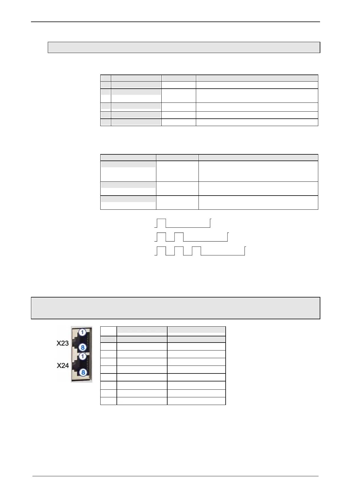
3.2.14. Ethernet Powerlink (Option I30) / EtherCAT (option I31) X23,
X24
RJ45 (X23) RJ45 (X24)
PIN in out
1 Tx + Tx +
2 Tx - Tx -
3 Rx + Rx +
4 - Reserved
5 - Reserved
6 Rx - Rx -
7 - Reserved
8 - Reserved
Wiring with Ethernet Crossover cable Cat5e (from X24 to X23 of the next device
without termination); for this, we recommend ourl SSK28 (see page 430, see page
445) interface cable.
Meaning of
the RJ45 LEDs (only for Ethernet Powerlink, I30)
Green LED (top): connection established (RPT_LINK/RX)
Yellow LED (bottom): Traffic (exchange of data) (Transmit / Receive Data)
(RPT_ERR)

 Loading...


