Motion control C3F_T40
286 192-121102 N04 June 2008
Boundary conditions:
The ReadStatus module helps detect, if the axis is in the error state.
An error will trigger the stop of the virtual axis, the curve cycle will stop, the curve
generator (C3_CamTableSelect) will continue.
After the stop of the master, the axis will also be at a standstill.
The error is acknowledged via input I5; the axis will be energized again (see also
the "AND" module at the input of MC_Power).
If the axis is energized again and input I5 is present, the axis is moved to the
current position of the curve output (MC_moveAbsolute) and at the end of the
movement it is coupled again with MC_CamIn.
The output "InSync" of the MC_CamIn (camin2) will re-start the virtual master and
the cycle is continued.
5.10.9.10 Application note: Drift
Correct scaling of the reference values helps prevent drift.
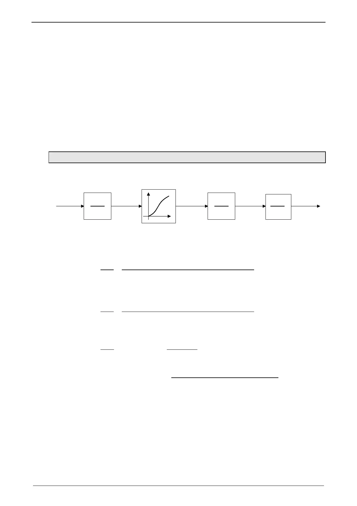
For this, it is necessary to consider the conversions of the position signal:
Z1
N1
N2
Z2
N3
Z3
MT
ST
Master
revolution
Master
units
Slave
units
Slave
revolution
Load
revolution
Gear box
Master / Slave / Load revolution: Master / Slave / Load revolutions:
Master / Slave units: Master / Slave - revolutions
Gear box: Gearbox
The rule for this is:
Z1
Travel distance per revolution master axis
numerator
N1
=
Travel distance per motor revolution master axis
denominator
(configured in the Compax3 ServoManager under "signal source")
Z2
Travel distance per revolution slave axis
numerator
N2
=
Travel distance per revolution – Slave axis
Denominator
(configured in the Compax3 ServoManager under "configuration")
Z3
Motor
N3
= transmission
ratio
Load
"Position Reset" Distance - Master
Axis (M_Units)
MT: Master clock
distance
"Position Reset" Distance - Master
Axis (Denominator)
MT is rounded to 3 decimal places.
ST: Slave clock distance

 Loading...


