Compax3F device description C3F_T40
30 192-121102 N04 June 2008
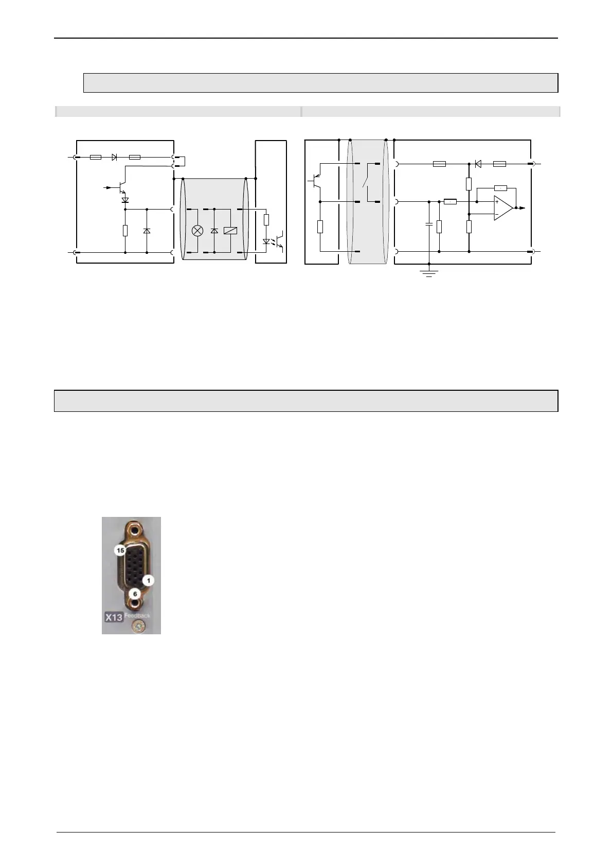
3.2.9.1 Connection of the digital Outputs/Inputs
Wiring of digital outputs Status of digital inputs
24V
0V
X12/2
18.2K
Ω
X12/15
X12/1
X12/11
SPS/
PLC
F2
F1
Compax3
24V
0V
100K
Ω
X12/1
X12/6
X12/15
10K
Ω
22K
Ω
22K
Ω
22K
Ω
SPS/PLC
F2
F1
10nF
Compax3
The circuit example is valid for all digital outputs!
The outputs are short circuit proof; a short circuit
generates an error.
The circuit example is valid for all digital inputs!
Signal level:
> 9.15V = "1" (38,2% of the control voltage applied)
> 8.05V = "0" (33.5% of the control voltage applied)
F1: delayed action fuse
F2: quick action electronic fuse; can be reset by switching the 24VDC supply off and on again.
3.2.10. Feedback (connector X13)
The following position sensors can be connected via X13:
1VSS SineCosine (max. 400Hz)
RS422 Encoder (max. 5MHz, or Step/Direction)
SSI (RS422)
Start / Stop (Time of Flight, RS422)
EnDat2.1

 Loading...


