Parker EME
Compax3F device description
192-121102 N04 June 2008 37
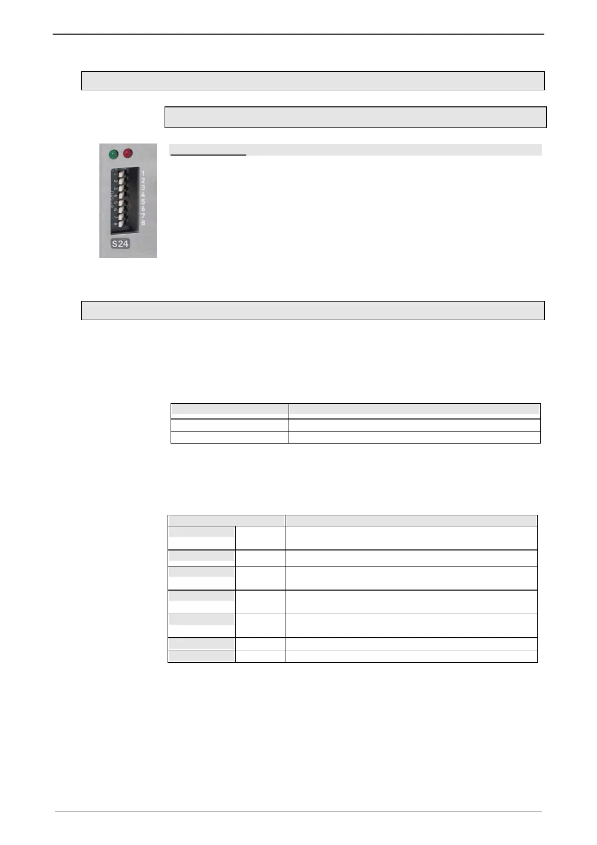
3.2.14.1 Set Ethernet Powerlink (option I30) bus address
Automatic address assignment with EtherCAT
Address setting
Values:
1: 2
0
; 2: 2
1
; 3: 2
2
; ... 7: 2
6
; 8: 2
7
Settings:
left: OFF
right: ON
(The address is set to 0 in the illustration)
Range of values: 1 ... 239
3.2.14.2 Meaning of the Bus LEDs (Ethernet Powerlink)
Red LED (right): Ethernet Powerlink error
LED is influenced by the transitions of the NMT - status diagram (for further details,
please refer to the Ethernet Powerlink Specification
http://www.parker.com/euro_emd/EME/download
s/compax3/EPL/epl2.0-ds-v-1-0-
0.pdf)
Error LED Transition
off => on NMT_CT11,NMT_GT6,NMT_MT6
on => off NMT_CT6, NMT_GT2, NMT_CT3, NMT_MT5
Green LED (left): Ethernet Powerlink Status
LED indicates the states of the NMT - status diagram (for further details, please
refer to the Ethernet Powerlink Specification
http://www.parker.com/euro_emd/EME/download
s/compax3/EPL/epl2.0-ds-v-1-0-
0.pdf)
Status LED status
off
off NMT_GS_OFF, NMT_GS_INITIALISATION,
NMT_CS_NOT_ACTIVE / NMT_MS_NOT_ACTIVE
flickering
flickering NMT_CS_BASIC_ETHERNET
single flash
Single
flash
NMT_CS_PRE_OPERATIONAL_1 /
NMT_MS_PRE_OPERATIONAL_1
double flash
Double
flash
NMT_CS_PRE_OPERATIONAL_2 /
NMT_MS_PRE_OPERATIONAL_2
triple flash
Triple
flash
NMT_CS_READY_TO_OPERATE /
NMT_MS_READY_TO_OPERATE
on
on NMT_CS_OPERATIONAL / NMT_MS_OPERATIONAL
blinking
flashing NMT_CS_STOPPED

 Loading...


