Parker EME
Setting up Compax3
192-121102 N04 June 2008 131
4.3.3.14 Output signal conditioning 0
In this chapter you can read about:
Conditioning Chain Symbols............................................................................................ 132
Object 2400.3: Upper limit of ocntrol signal ..................................................................... 132
Object 2400.4: Lower limit of the control signal ............................................................... 132
Object 2400.6: Output Offset ........................................................................................... 133
Object 2400.7: Replacement value (inactive Chain 0)
..................................................... 133
Object 2401.4: Gain factor positive.................................................................................. 133
Object 2401.5: Gain factor negative ................................................................................ 134
Object 2401.7: Gain positive direction (Force-/Pressure- control)................................... 134
Object 2401.8: Gain negative direction (Force-/Pressure- control) ................................. 134
Object 2401.6: Inversion [on/off]...................................................................................... 135
Object 2402.1: Pressure Compensation [on/off].............................................................. 135
Object 2403.1: Characteristic flow [on/off] ....................................................................... 135
Object 2405.1: Deadband [on/off].................................................................................... 136
Object 2405.2: Deadband A-side..................................................................................... 136
Object 2405.3: Deadband B-side..................................................................................... 136
Object 2405.4: Deadband threshold value ...................................................................... 137
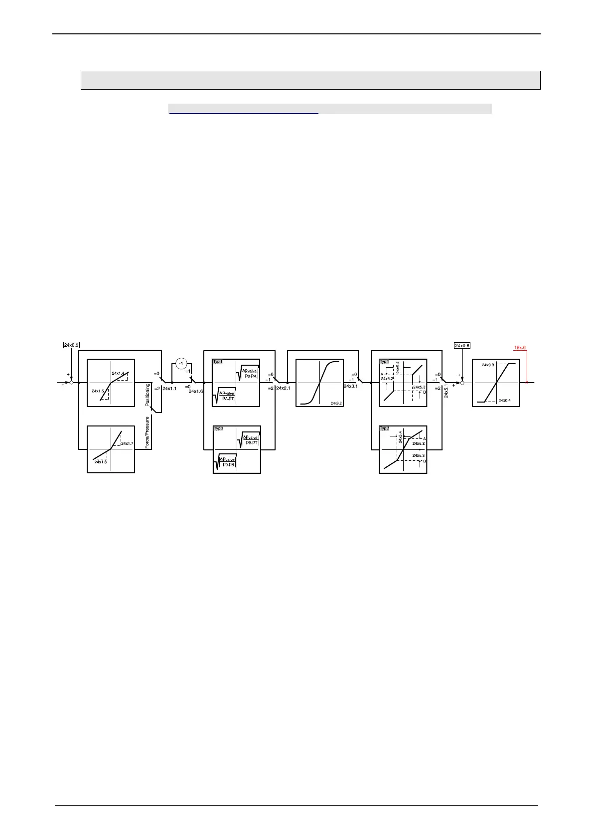
In order to linearize the valve as well as the entire control path 4 linearization
chains (conditioning chains => output signal conditioning) are available.
Layout of the path linearization (Conditioning Chains):
The Conditioning Chains are set via objects in the
optimization window (see page
88).
The "x" in the object
s given in the signal image depends on the conditioning chains
to be parameterized:
x = 0,1,2,3 = Conditioning Chain No.
In the
Compax3F structure image (see page 45) you can see how the
Conditioning Chains are integrated in the total structure.
Below you can find the descriptions of the individual objects.
Objects of the
conditioning chains:

 Loading...


