Compax3F device description C3F_T40
26 192-121102 N04 June 2008
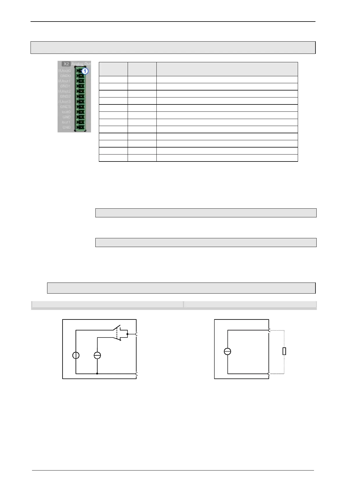
3.2.5. Analog Output (plug X2)
Plug X2
Pin
Descripti
on
Combicon 3,81mm; female connector
1 I/U Aout0 ±10V/10mA or 4..20mA
2 GND 0
3 I/U Aout1 ±10V/10mA or 4..20mA
4 GND 1
5 I/U Aout2 ±10V/10mA or 4..20mA
6 GND 2
7 I/U Aout3 ±10V/10mA or 4..20mA
8 GND 3
9 Iout 0 +/-100mA current output 0
10 GND
11 lout 1 +/-100mA current output 1
12 GND
Terminating resistor:
Voltage +/-10V: ≥ 1000Ω
Current 4..20mA: ≤ 600Ω
Current 100mA: ≤ 100Ω
All outputs are short-circuit proof.
Requirement: Connection cable
Use shielded cables.
Shield connection of the cables
The cable should be fully screened and connected to the Compax3 housing. We
offer a special Shield connecting terminal (see page 432) as accessory item
(ZBH./...).
3.2.5.1 Wiring of analog outputs
Output I/U Aout0 Output Iout0
X2/2
0...20mA*+/-10V
(10mA)
X2/1 I/Uout0
GND0
Co
pax3 Fluid
* 20mA to max. 450Ω
X2/10
+/-100mA*
X2/9 Iout0
GND
Co
pax3 Fluid
* at RL<=180Ω
Aout0 to Aout3 do have the same wiring!
Pin assignment (see page 26) X2
Iout0 and Iout
1 (X2/11 and X2/12) have the same
wiring!

 Loading...


