Parker EME
Compax3F device description
192-121102 N04 June 2008 25
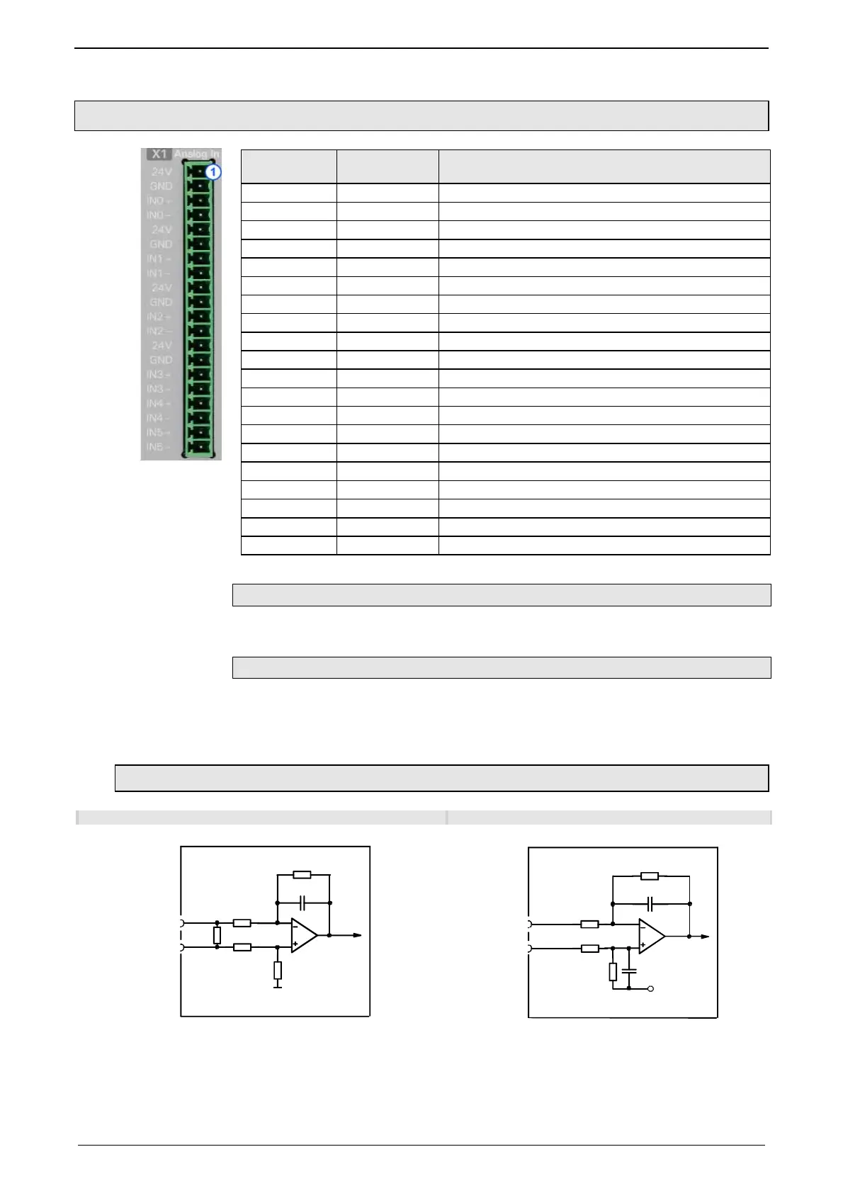
3.2.4. Analog Input (plug X1)
Connector X1
Pin
Description Combicon 3,81mm; female connector
1 24V Supply Sensor 0
2 GND Supply Sensor 0
3 IN0+ Signal Sensor 0 +
4 IN0- Signal Sensor 0 -
5 24V Supply Sensor 1
6 GND Supply Sensor 1
7 IN1 + Signal Sensor 1 +
8 IN1 - Signal Sensor 1 -
9 24V Supply Sensor 2
10 GND Supply Sensor 2
11 IN2 + Signal Sensor 2 +
12 IN2 - Signal Sensor 2 -
13 24V Supply Sensor 3
14 GND Supply Sensor 3
15 IN3 + Signal Sensor 3 +
16 IN3- Signal Sensor 3 -
17 IN4+ +/-10V Input 4
18 IN4- +/-10V Input 4
19 IN5+ +/-10V Input 5
20 IN5- +/-10V Input 5
Requirement: Connection cable
Use shielded cables.
Shield connection of the cables
The cable should be fully screened and connected to the Compax3 housing. We
offer a special Shield connecting terminal (see page 432) as accessory item
(ZBH./...).
3.2.4.1 Wiring of the analog inputs
Input IN0 Input IN4
10pF
200KΩ
200KΩ
In0-
200KΩ
X1/4
200KΩ
In0+
X1/3
2
5
0
Ω
Co
pax3 Fluid
1nF
22.1KΩ
100KΩ
In4+
22.1KΩ
X1/17
100KΩ
1nF
In4-
X1/18
2.5V
Compax3 Fluid
IN0 to IN3 do have the same wiring!
Pin assignment (see page 25) X1
IIN4 and IN5
(X11/19 and X11/20) have the same
wiring!

 Loading...


