Setting up Compax3 C3F_T40
98 192-121102 N04 June 2008
1: Selection of the optimization tab
2: Selection of the optimization value
3: List of the optimization objects, with object name and object number
4: Command VP for accepting a changed optimization object.
Yellow background indicates that an object has been changed, was however not
yet set to valid with VP.
5: Command WF for permanently saving the changed obejcts (also after mains
off/on)
6: Acknowledging a Compax3 error.
7: Setting options:
Standard / Advanced mode
Load protocol to clipboard, load into notepad or delete
8: Editing window: The value of an object selected with the aid of the mouse (in 3)
can here be edited and confirmed with return.
9: Additional functions, depending on the Compax3 technology function.
4.3.3.1 Preparatory settings for the controller alignment
In this chapter you can read about:
Configuring the device ....................................................................................................... 98
Checking the feedback direction and the valve output polarity.......................................... 98
Compensation of non-linearities of the distance
................................................................ 99
Checking the open loop gain ........................................................................................... 101
Filter alignment ................................................................................................................ 101
Controller optimization ..................................................................................................... 102
Configuring the device
The configuration settings must be made before with the aid of the Configuration
Wizard.
Optimization takes place in the
optimization window (see page 88).
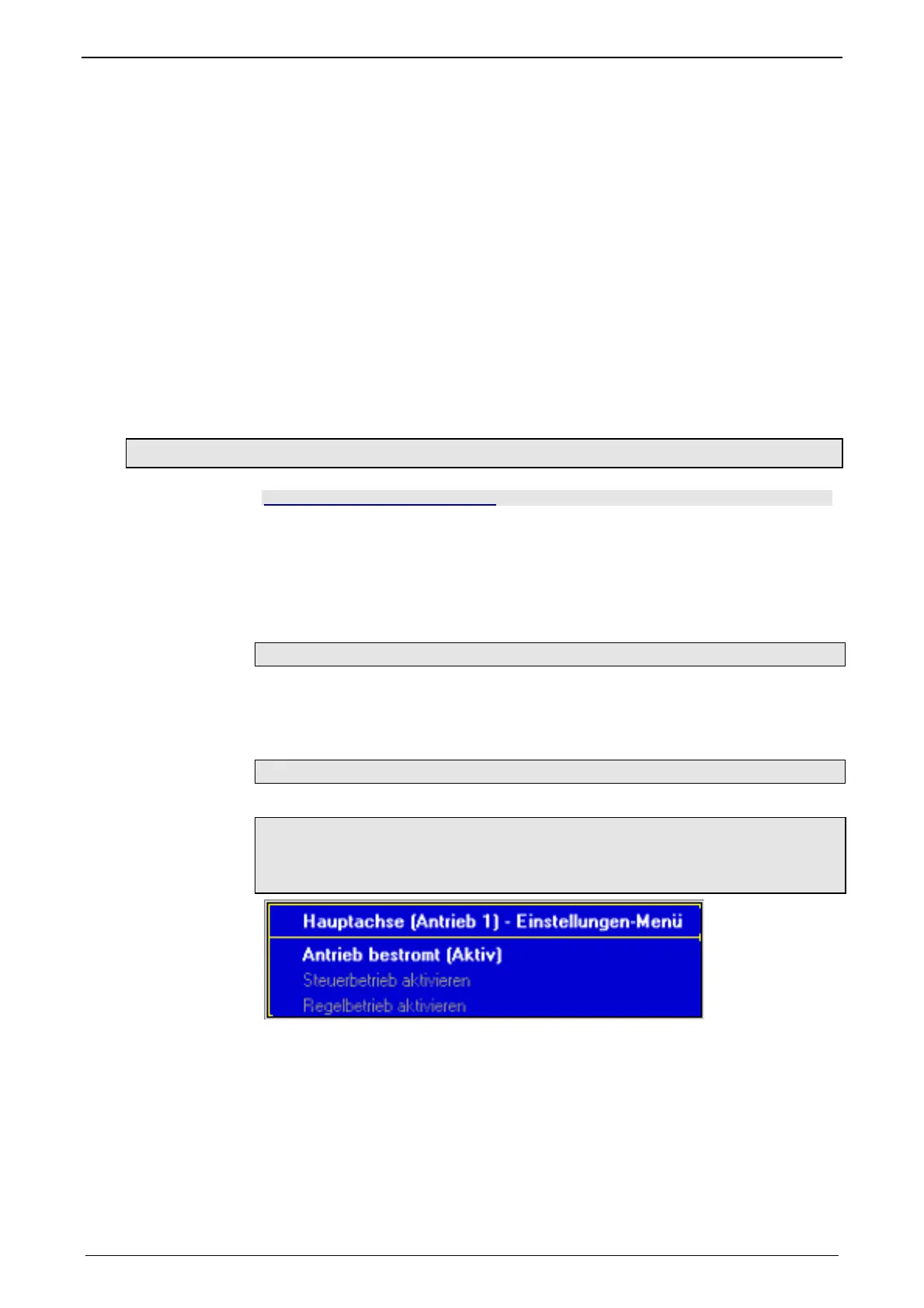
Checking the feedback direction and the valve output polarity
Feedback direction and valve polarity are verified in the open loop.
ATTENTION:
In the open loop operation, the drive axis might drift, as the position
controller is deactivated!

 Loading...


