Parker EME
Setting up Compax3
192-121102 N04 June 2008 89
4.3.2. Scope
In this chapter you can read about:
Monitor information.............................................................................................................89
User interface .....................................................................................................................90
Example: Setting the Oscilloscope.....................................................................................95
The integrated oscilloscope function features a 4-channel oscilloscope for the
display and measurement of signal images (digital and analog) consisting of a
graphic display and a user interface.
Special feature:
in the single mode you can close the ServoManager after the activation of the
measurement and disconnect the PC from Compax3 and upload the measurement
into the ServoManager later.
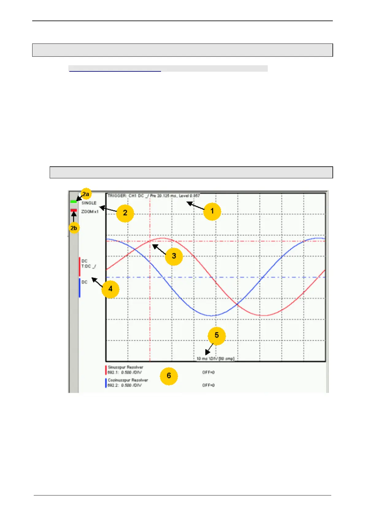
4.3.2.1 Monitor information
1: Display of the trigger information
2: Display of the operating mode and the zoom setting
2a: Green indicates, that a measurement is active (a measurement can be
started or stopped by clicking here).
2b: Active channel: the active channel can be changed sequentially by clicking
here (only with valid signal source).
3: Trigger point for Single and Normal operating mode
4: Channel information: Type of display and trigger settiing
5: X-DIV: X deviation set
6: Single channel sources

 Loading...


