Parker EME
Motion control
192-121102 N04 June 2008 181
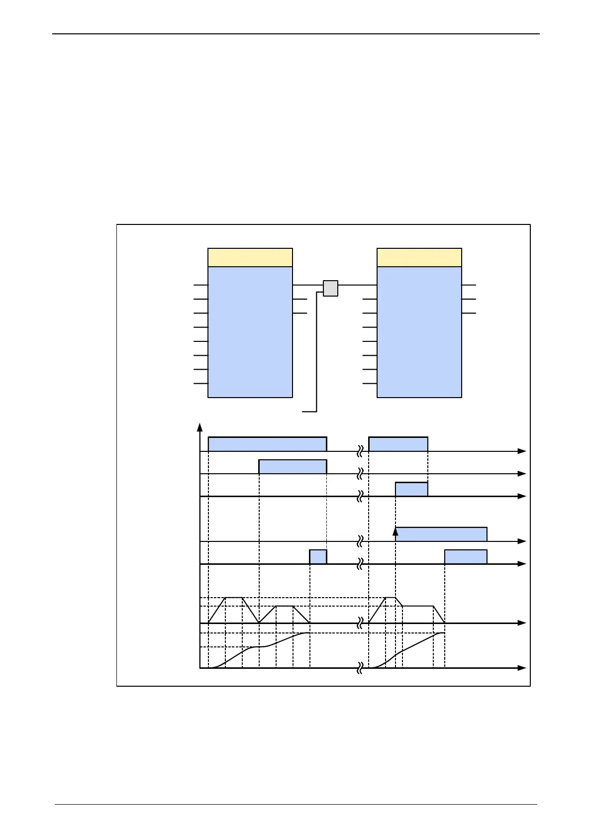
The following illustration shows two examples of the combination of two
MC_MoveAbsolute modules.
The left part (a) of the time diagram shows a case in which the second function
module (FB) is executed after the first function module..
When the first function module has reached Position 60, the "Done" output gives
the execution command to the second function module, which then moves to
Position 100.
The right part (b) of the diagram shows a case in which the second function
module is activated while the first function module is being executed. The first
function module is automatically interrupted..
The second function module moves directly to position 100 whether or not
position 60 of the first function module has already been reached.
Execute
Position
Done
Error
MC_MoveAbsolute
Command
Aborted
Velocity
Acceleration
Deceleration
Jerk
JerkDecel
Axis
Execute
Position
Done
Error
MC_MoveAbsolute
Command
Aborted
Velocity
Acceleration
Deceleration
Jerk
JerkDecel
Axis
OR
Test
1. Instanz
First motion
2. Instanz
Second motion
100. 0
200. 0
100
100
1000
1000
AXIS_REF_
LocalAxis
60. 0
300. 0
100
100
1000
1000
AXIS_REF_LocalAxis
go
1. Instanz
First motion
Execute (go)
Done
t
t
t
t
t
t
t
1
0
1
0
1
0
1
0
1
0
0
100
0
200
300
Command-
Aborted
Execute (Test)
Done
Velocity
absolute Position
absolute position
2. Instanz
Second motion
Bewegungsablauf
Moving diagram
ab
60

 Loading...


