Parker EME
Motion control
192-121102 N04 June 2008 187
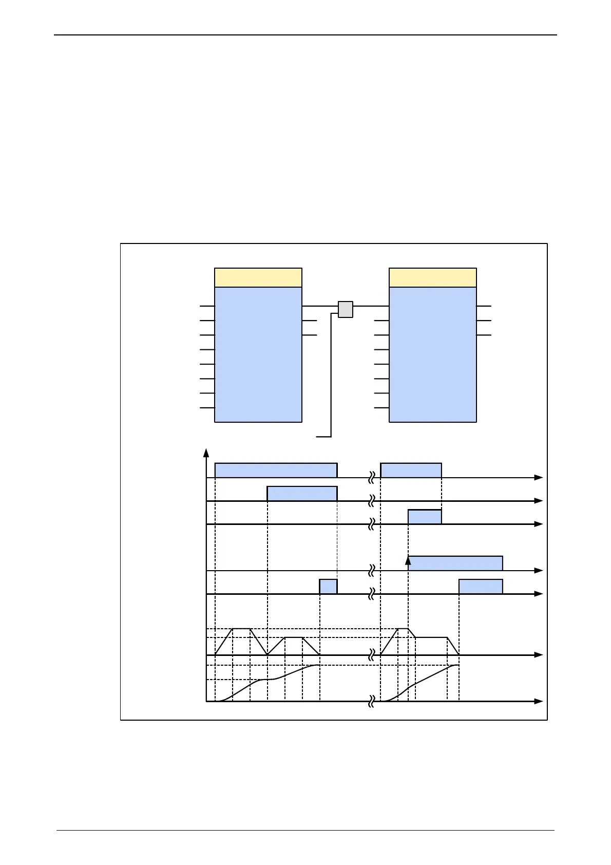
The following illustration shows two examples of the combination of a
MC_MoveAbsolute and an MC_MoveAddititve module.
The left part (a) of the time diagram shows a case in which the second function
module is executed after the first function module.
After the first function module has traveled to Position 60, the "Done" output gives
the execution command to the second FB, which then moves on another 40 units
The right part (b) of the diagram shows a case in which the second function
module is activated while the first FB is being executed. Because the second
module is started during the execution of the first FB, the first FB is automatically
interrupted.
The second function module adds the missing units that are still lacking for the
first module and the moves an additional 40 units with the new predefined
settings.
Execute
Position
Done
Error
MC_MoveAbsolute
Command
Aborted
Velocity
Acceleration
Deceleration
Jerk
JerkDecel
Axis
Execute
Distance
Done
Error
MC_MoveAdditive
Command
Aborted
Velocity
Acceleration
Deceleration
Jerk
JerkDecel
Axis
OR
Test
1. Instanz
First motion
2. Instanz
Second motion
40. 0
200. 0
100
100
1000
1000
AXIS_REF_
LocalAxis
60. 0
300. 0
100
100
1000
1000
AXIS_REF_LocalAxis
go
1. Instanz
First motion
Execute (go)
Done
t
t
t
t
t
t
t
1
0
1
0
1
0
1
0
1
0
0
100
0
200
300
Command-
Aborted
Execute (Test)
Done
Velocity
Position
2. Instanz
Second motion
Bewegungsablauf
Moving diagram
ab
60

 Loading...


