Parker EME
Motion control
192-121102 N04 June 2008 189
Example
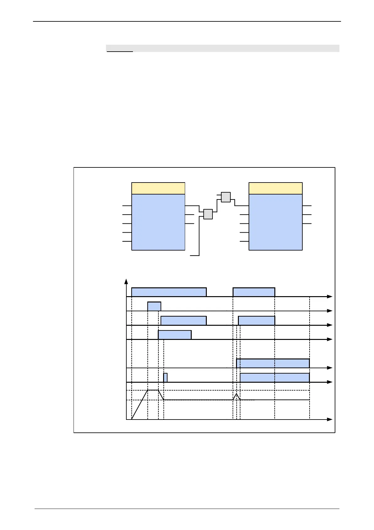
The following illustration shows two examples of the combination of two
MC_MoveVelocity modules.
The left part (a) of the time diagram shows a case in which the second function
module is executed after the first function module.
After the first function module has accelerated to a speed of 3000, the
"InVelocity" output, AND-linked with the "Next" signal gives the execution
command to the second FB, which then slows to a speed of 2000.
The right part (b) of the diagram shows a case in which the second FB is
activated while the first function module is being executed. Because the second
module is started during the execution of the first FB, the first FB is automatically
interrupted.
During the acceleration of the first module, the second module slows again
similarly to a speed of 2000 without the speed of the first module having been
reached.
Run InVelocity
Error
MC_MoveVelocity
Command
Aborted
Velocity
Acceleration
Direction
Axis
Run
Velocity
InVelocity
Error
MC_MoveVelocity
Command
Aborted
Acceleration
Direction
Axis
OR
Next
1. Instanz
First motion
2. Instanz
Second motion
2000
100
"MC_Direction_
Positive"
3000
100
"MC_Direction_Positive"
AXIS_REF_LocalAxis
go
1. Instanz
First motion
Velocity
Next
t
t
t
t
t
t
1
0
1
0
1
0
1
0
1
0
0
2000
3000
Command Aborted
Test
Finish = InVelocity
Velocity
2. Instanz
Second motion
Bewegung
Motion
&
Test
Execute (go)
t
1
0
1
Finish
AXIS_REF_
LocalAxis
a
b

 Loading...


