Motion control C3F_T40
228 192-121102 N04 June 2008
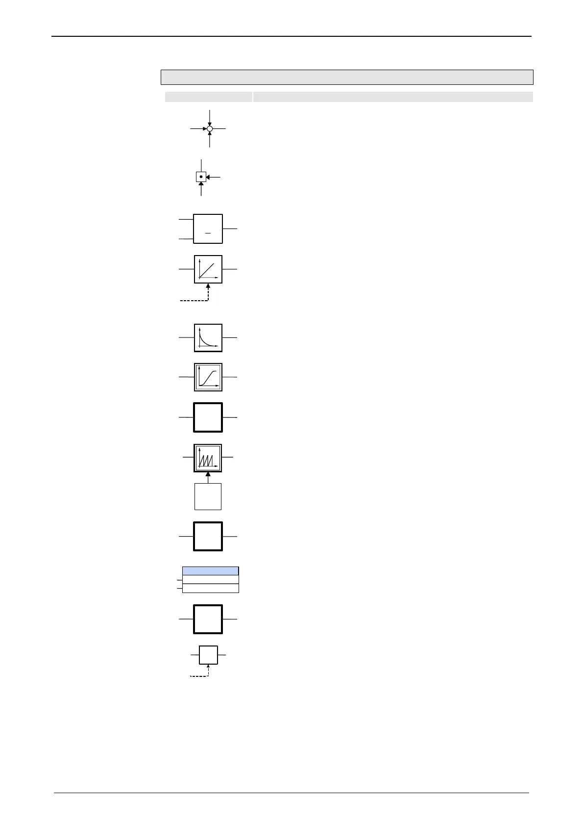
Symbols of the signal image
Symbol Description
+
+
+
a
b
c
d
Point of addition:
d = a + b + c
a
b
c
Point of multiplication:
c = a * b
b>a
a
b
Comparison:
If b >= a, then output active
StartValue=0
Integrator
Output signal = ∫(Input signal)*dt
The output signal is the integral (sum over time) of the input
signal
”Start value=0” will set the output to 0; this is triggered by
activating ”Execute” of an IEC module.
Differentiator
Output signal = d(input signal)/dt
The output signal is the derivation (gradient) of the input signal
S
M
non-linear curve function Slave / Master
Slave-Position = f (Master-Position)
Control-
loop
Closed control loop
Input: Setpoint Position
Output: Actual position
R
Reset function
Output signal is reset to 0 after value ”R”.
Value R can be taken in the signal image.
Setpoint-
generator
Command value generator
Generates the desired setpoint process (e.g. when coupling
into a curve)
C3_CamTableSelect
MasterCycle
SlaveCycle
IEC function module
with module name and input values
BackStop
Back stop
Prevents a declining master signal
(Functions of
C3_MasterControl (see page 237))
SH
t
Sampling-holding-function (SH: Sample & Hold)
The input value of the SH member is written to the output with
trigger signal t.

 Loading...


