Parker EME
Setting up Compax3
192-121102 N04 June 2008 63
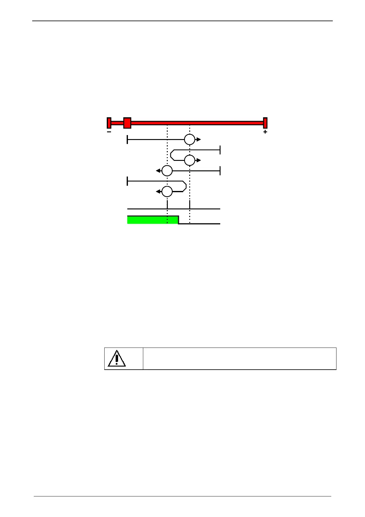
MN-M 5.6: MN initiator = 1 on the negative side
The MN initiator can be positioned at any location within the travel range. The
travel range is then divided into 2 contiguous ranges: one range with deactivated
MN initiator (positive part of the travel range) and one range with activated MN
initiator (negative part of the travel range).
When the MN initiator is inactive (signal = 0) the search for the machine reference
is in the negative travel direction.
MN-M 5:The 1st motor zero point with MN proximity switch = "0" is used as MN.
MN-M 6:The 1st motor zero point with MN initiator = "1" is used as MN.
6
5
5
6
1
2
1: Motor zero point
2: Logic state of the home switch
With direction reversal switches
Machine zero modes with a home switch which is activated in the middle of the
travel range and can be deactivated to both sides.
The assignment of the direction reversal switches (see page 74) can be
cha
nged.
Function Reversal via Following error threshold
If no direction reversal switches are available, the reversal of direction can also be
performed during the machine zero run via the function ”direction reversal via
Following error threshold"
Here the drive runs towards the mechanical limit mounted at the end of the travel
range.
When the settable Following error threshold is reached, the drive is braked and
changes the travel direction.
Caution!
Wrong settings can cause hazard for man and machine.
It is therefore essential to respect the following:
Choose a low machine zero speed.
Set the machine zero acceleration to a high value, so that the drive changes
direction quickly, the value must, however, not be so high that the limit threshold
is already reached by accelerating or decelerating (without mechanical limitation).
The mechanical limitation as well as the load drain must be set so that they can
absorb the resulting kinetic energy.
With motor zero
point, without
direction reversal
switches

 Loading...


