DRUM UNIT
2-50
A229 SM
Drum potential sensor calibration
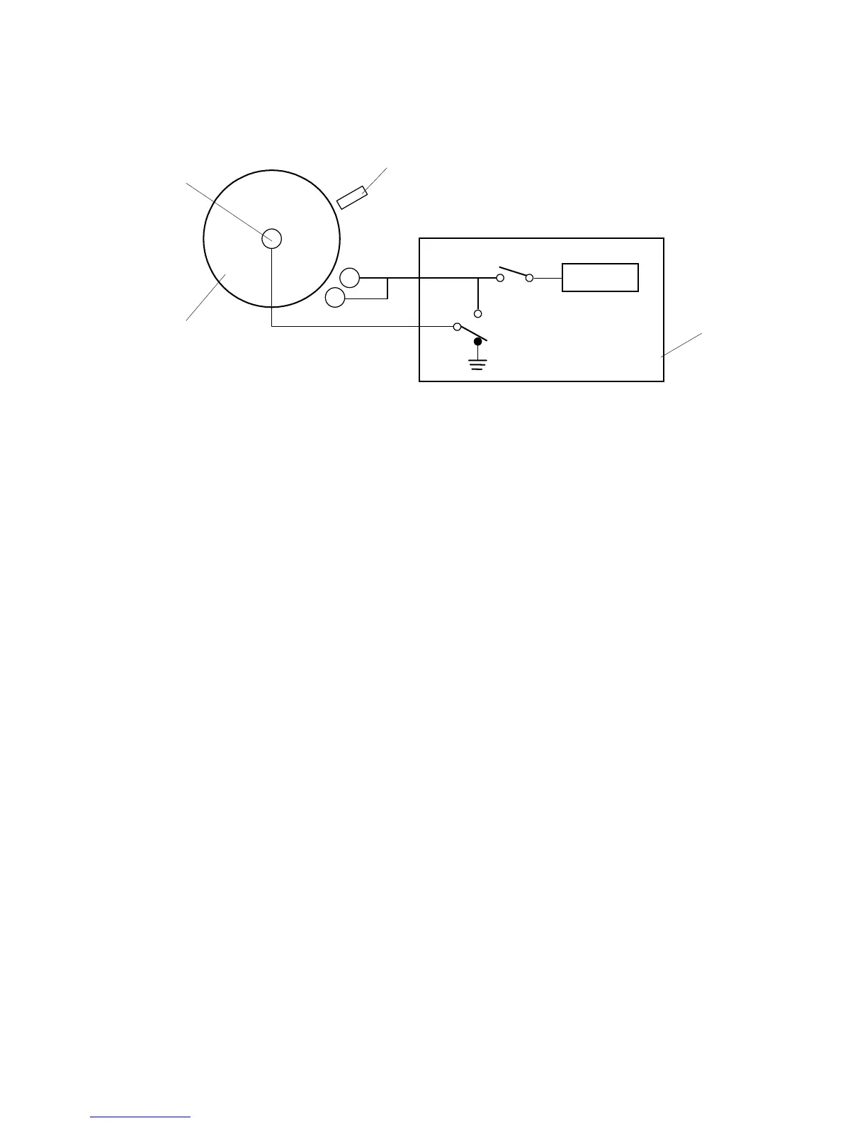
The drum potential sensor [A] detects the electric potential of the drum surface [B].
Since the output of the sensor is affected by environmental conditions, such as
temperature and humidity, the sensor needs recalibration at times. This is done
during process control initial setting.
The development power pack [C] has two relay contacts. Usually RA102 grounds
the drum. However, to calibrate the sensor, the SBICU switches RA102 and RA101
over, which applies the power pack output voltage to the drum shaft [D].
The machine automatically calibrates the drum potential sensor by measuring the
output of the sensor when –200V and –700V are applied to the drum. From these
two readings, the machine can determine the actual drum potential from the
potential sensor output that is measured during operation.
During calibration, if the rate of change in drum potential sensor response to
applied voltage is out of the target range, SC370-02 is logged and auto process
control turns off. The V
G
and LD power adjustments are skipped; V
G
is set to the
value stored in SP2-001-01, and LD power is set to the values stored in SP2-103.
V
SG
adjustment
This calibrates the ID sensor output for a bare drum to 4.0
±
0.2V. It does this by
changing the intensity of the light shining on the drum from the sensor. This is done
automatically during process control initial setting, and it can also be done
manually with SP3-001-002.
If the ID sensor output cannot be adjusted to within the standard, SC350 is logged
and toner density control is done using the TD sensor and image pixel count.
For details of how the machine determines an abnormal sensor detection, see
section 6 (Troubleshooting).
-200/-700
RA102
RA101
A229D641.WMF
[A]
[B]
[C]
[D]
Rev. 6/3/99



 To Next Page