ELECTRICAL COMPONENT DESCRIPTIONS
A229 8-4 SM
1.4 ELECTRICAL COMPONENT DESCRIPTIONS
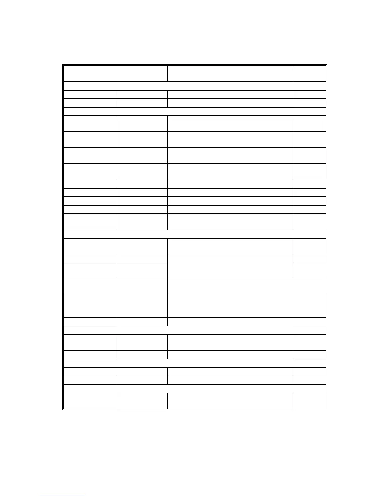
Symbol Name Function
Index
No.
Motors
M1 LCT Drives all rollers. 6
M2 Lift Drives the paper tray up or down. 14
Sensors
S1
Paper End Informs the copier when the paper has
run out.
21
S2
Paper Feed Detects the copy paper coming to the
relay roller and checks for misfeeds.
1
S3
Lift
Detects when the paper is at the correct
paper feed height.
2
S4
Down Detects when the tray is completely
lowered, to stop the LCT motor.
15
S5 Paper Height 1 Detects the paper height. 10
S6 Paper Height 2 Detects the paper height. 11
S7 Paper Height 3 Detects the paper height. 12
S8 Near End Detects the paper height. 9
S9
Paper Position Detects when the top of the paper stack
is at the correct position for paper feed.
20
Switches
SW1
Tray Cover 1
Detects whether the tray cover is opened
or not.
16
SW2 Tray Cover 2 17
SW3
Tray Cover 3
Ensures that +24V can be passed to the
lift motor whether the cover is open or
closed.
18
SW4
Feed Unit
Cover 1
Detects whether the feed unit cover is
opened or not.
7
SW5
Feed Unit
Cover 2
Ensures that +24V can be passed to the
lift motor whether the cover is open or
closed.
8
SW6 Down Lowers the LCT bottom plate if pressed. 19
Solenoids
SOL1
Pick-up Controls up-down movement of the pick-
up roller.
3
Magnetic Clutches
MC1 Paper Feed Drives the paper feed roller. 5
MC2 Relay Drives the relay roller. 4
PCBs
PCB1
LCT Interface
Controls the LCT and communicates with
the copier.
13



 To Next Page