COPY IMAGE ADJUSTMENTS: PRINTING/SCANNING
SM 5-107 A229
Replacement
and
Adjustment
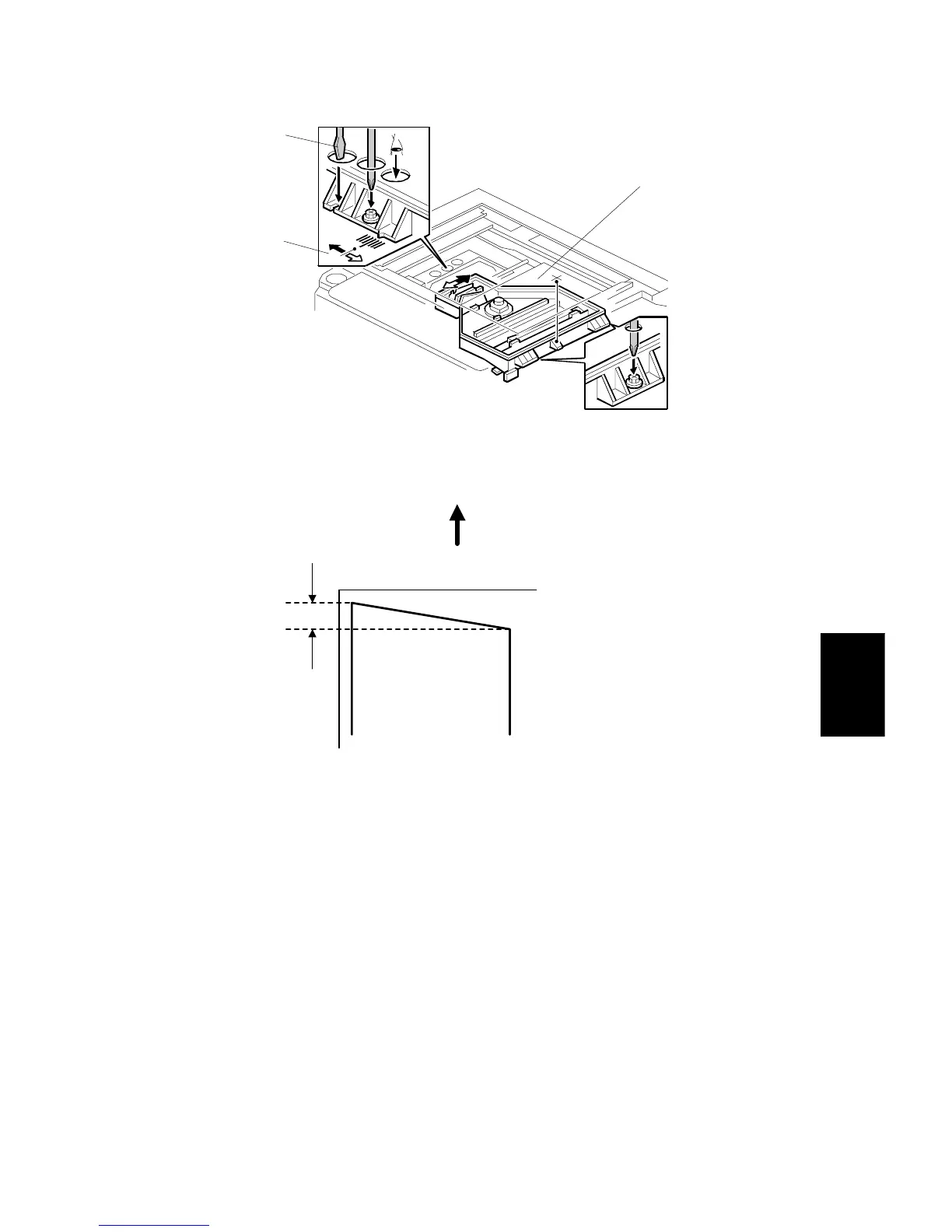
6. Adjust the laser unit position using a flat screwdriver [A] as shown.
If the right side of the trimming area pattern is down by about 1 mm as shown
[B], the laser unit should be rotated about one tick mark in the direction of the
black arrow as shown [C]. If the opposite side is down, adjust in the opposite
direction.
NOTE:
The laser unit rotates around the point [D].
7. Tighten the three screws to secure the laser unit.
8. Replace the caps and exposure glass.
9. Print the trimming area pattern to check the image. If it is still skewed, repeat
steps 2 to 8.
A229R535.WMF
1 mm
Feed Direction
A229R591.WMF
[B]
[A]
[C]
[D]
[B]