TIMING CHART AND MISFEED DETECTION
A229 10-10 SM
1. On check:
J1: The entrance sensor does not activate within 2460 pulses after the exit sensor
of the main machine has been activated.
J2: The relay sensor does not activate within 1965 pulses after the entrance
sensor has been activated.
J3:
The proof tray exit sensor does not activate within 1665 pulses after the
entrance sensor has been activated.
J4:
The bridge relay sensor does not activate within 1954 pulses after the entrance
sensor has been activated.
J5: The appropriate tray exit sensor does not activate within the appropriate
number of pulses (see below) after the relay sensor has been activated.
J5 jam timing
Tray
Exit
Sensor
Sensor 1 Sensor 2 Sensor 3
Tray No.123456789
Pulses 72 139 176 206 242 273 304 343 375
2. Off check
J6: A sensor does de-activate within the specified number of pulses after that
sensor has been activated.
Number of pulses = Paper length (in the paper feed direction) x 1.5
1 pulse = 0.1707 mm
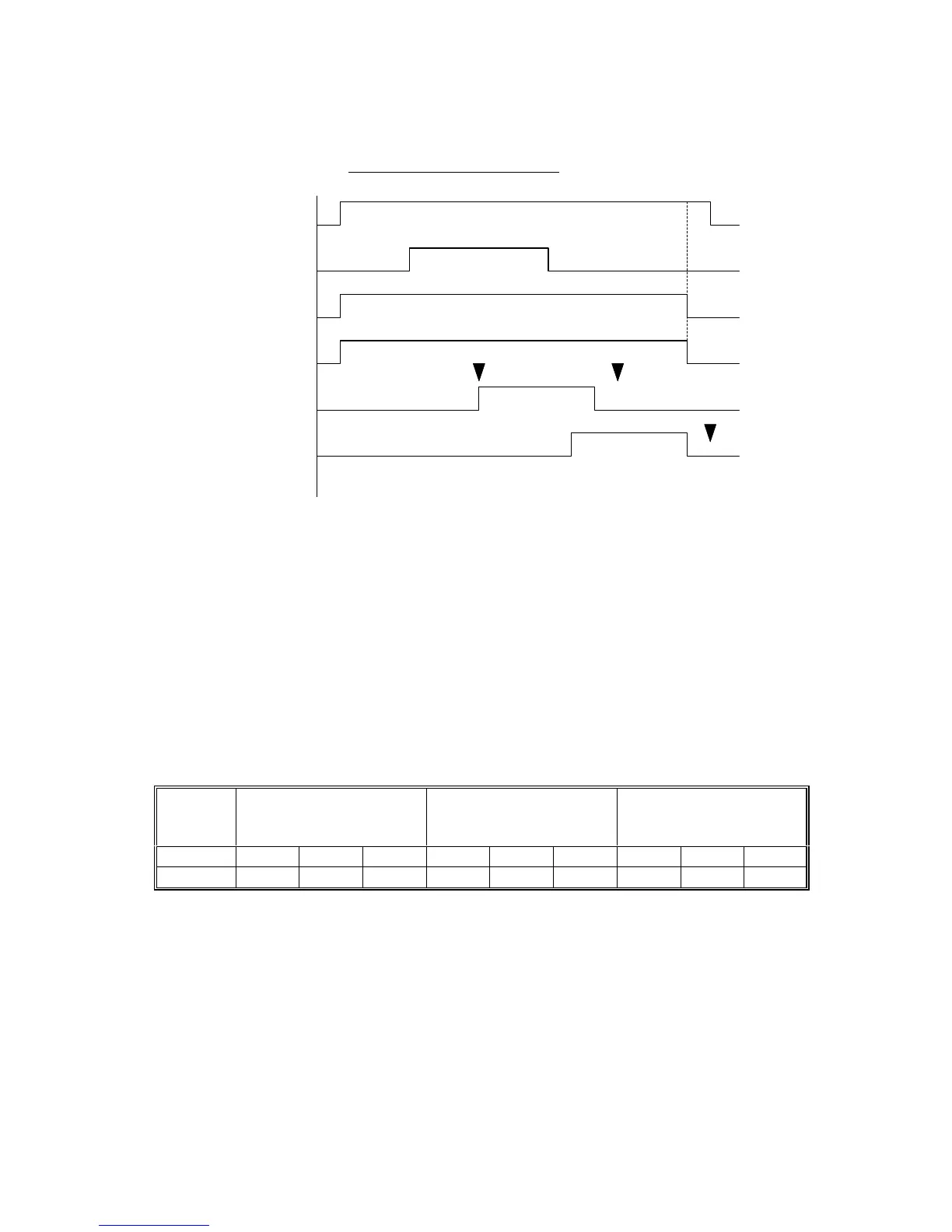
Transport Motor
Entrance Sensor
Proof Junction
Gate Sol.
Relay Junction
Gate Sol.
Bridge Relay
Sensor
Bridge Exit Sensor
A4 Sideways (to Bridge Unit)
J4
J6
J6
G909D501.WMF