Pamux User’s Guide 21
SETTING UP A B4 STATION
This section describes how to install the B4 digital I/O brain board on a compatible mounting rack. It also
discusses B4 configuration issues, including how to set jumpers for the address, watchdog, and reset
line. Finally, it addresses how to install a terminator board when a B4 station is at one end of a Pamux
system and describes the LED indicators.
INSTALLING THE B4 ON A MOUNTING RACK
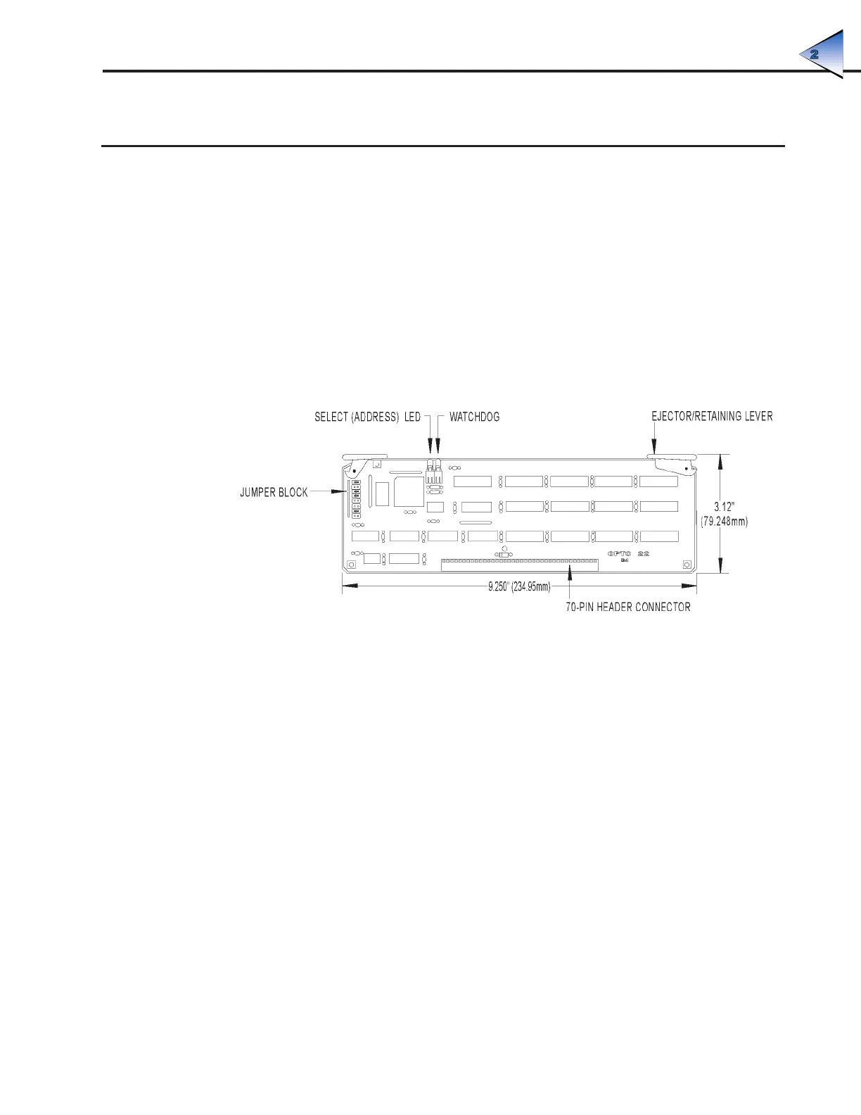
The B4 brain board measures 9.25 by 2.9 inches. It includes a 70-pin box connector along its bottom
edge to attach to a digital I/O mounting rack. Two levers are located on opposite corners of the board.
These levers operate with the card guides on the mounting rack to hold the brain board in place or to
help release it from the rack.
Figure 2-4 is a detailed illustration of the B4 along with its dimensions.
Figure 2-4: Dimensions of the B4 Brain Board
The B4 can be installed in either of two I/O mounting racks:
• G4PB32H — 32 channels of single-point G4 I/O
• PB32HQ — 32 channels of quad pak I/O (8 modules, 4 points per module)
The G4PB32H mounting rack uses single-point digital modules. It offers a dense footprint and
point-by-point I/O configuration flexibility.
The PB32HQ also offers a dense footprint but uses Opto 22 quad pak modules. Each quad pak contains
four discrete points of I/O in one package. The PB32HQ is thus configured in four-point increments.
Figure 2-5 shows how the B4 brain board is installed on either mounting rack.
SYSTEM SETUP