Atmospheric Single-Arm Robot Manual
4000-0016 Rev A
42
Accessing a User Interface
Equipe recommends that each operator control station that can initiate
robot motion, has a readily accessible EMERGENCY STOP or EMO
device. This includes the Teach Pendant; the S2-93A compliant TTR 200
has a red EMS button. Or, use the EQT 32 interface on a personal
computer.
Refer to the User Interface Manual for details on using the EQT 32
interface and the Teach Pendant. You cannot use the EQT 32 interface
and the Teach Pendant simultaneously.
Before connecting a Teach Pendant or installing the EQT 32 interface,
follow these instructions to ready the controller.
1. Verify that all cables are plugged into the correct connectors in the
correct orientation. Make sure they are securely fastened, using the
integral jack screws supplied with the cables as needed.
2. Exit the restricted envelope before you apply power.
3. Power up the controller.
4. After boot-up, check the indicator LEDs located at the front of the
controller. The following conditions indicate a “normal” condition:
• The green LED is ON.
• The yellow LED is flashing.
• The red LED remains ON until the amplifiers are enabled.
Connecting the Teach Pendant
If you have a TTR 200, refer to Appendix B: Circuit Drawings for
information on converting the TTR 200 DB15 connector to an RJ12
connector.
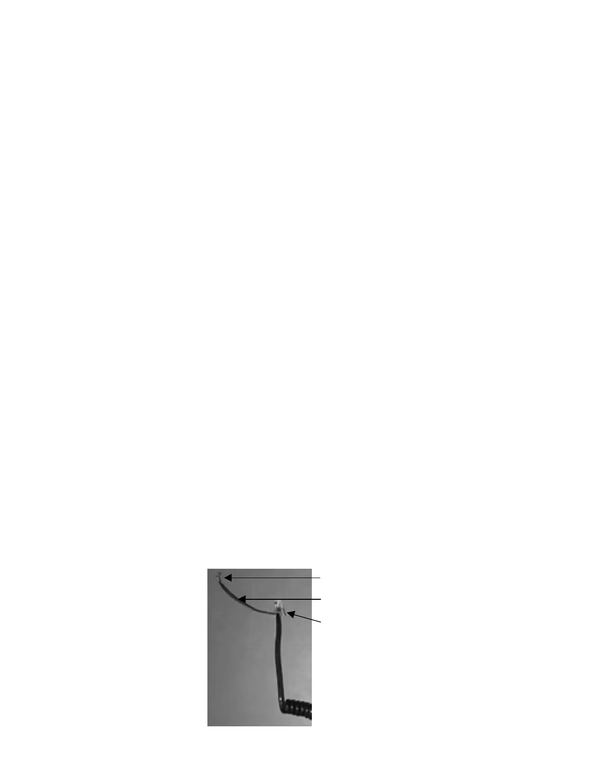
To avoid potential ESD and RFI problems, Equipe provides a shielded
Grounding strap
RJ12 connector
#6 ring lug