Operations and Maintenance Manual Mechanical Maintenance Procedures
Version 1.2 - June 2004 11 - 23
b. Using a 3/4-in. open end wrench, rotate the screw as needed to meet the
goal.
Rotating the screw clockwise lowers the side of the spindle nearest the left
side of the machine.
Rotating the screw counterclockwise raises the side of the spindle nearest
the left side of the machine.
Front to Rear
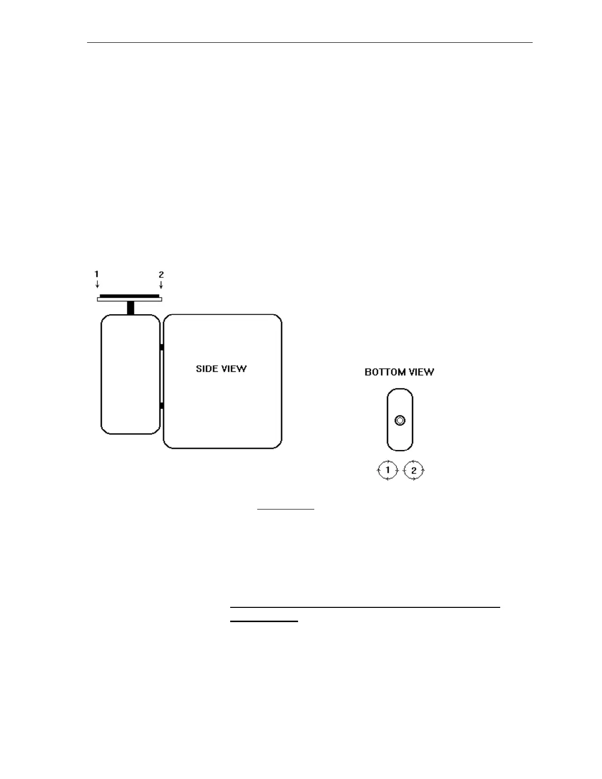
Figure 11-2 Lower Spindle Front to Rear Adjustment
4. Rotate the level to a front to rear position on the left work chuck mounting
plate (one end pointing toward the front of the machine cabinet and the other
end pointing toward the rear).
5. Read the level and adjust the position of the spindle assembly as needed to
meet the goal.
GOAL: The reading of the level should be centered within the
level's marks.