Operations and Maintenance Manual Physical Description
Version 1.2 - June 2004 3 - 15
SUBASSEMBLIES
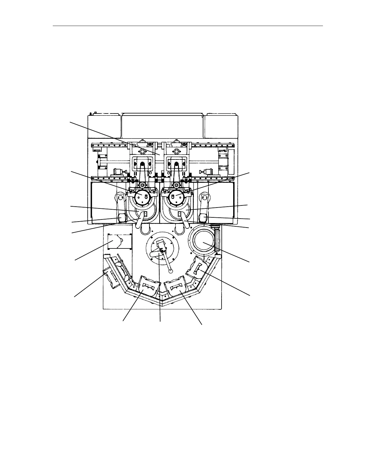
Figure 3-5, shown below, is a top view of the Model 7AF Wafer Grinder. The labeled
subassemblies participate in the wafer grinding process and manipulation of the wafers.
Figure 3-5 Wafer Grinder Subassemblies
1
2
3
4
5
6
7
8
9
10
11
12
13
14
15
16
1 Bridge Assembly 9 Right Work Chuck
2 Coarse Spindle 10 Pre-Aligner
3 Fine Spindle 11 Send 1 Cassette Turret
4 Left Digital Measurement Probe 12 Send 2 Cassette Turret
5 Right Digital Measurement Probe 13 Receive 2 Cassette Turret
6 Left Conditioning Arm 14 Receive 1 Cassette Turret
7 Right Conditioning Arm 15 Spin-Rinse Station
8 Left Work Chuck 16 Robot