Atmospheric Single-Arm Robot Manual
4000-0016 Rev A
13
To recover from EMS/MOFF, inspect the system for any damage or
interfering components, pull out the STOP button, start up the system,
turn on servo motors for all axes (SVON), and home all axes.
To enable EMS/MOFF, activate pin 20 (+) and pin 3 (-) on the DB37
connector with 24 volts dc (S2-93A systems) or 5 volts dc (non-S293A
systems) wired normally closed, as shown in the Emergency Stop
Circuit and Interconnect diagram.
For more details, refer to Appendix B: Circuit Drawings. To custom
configure other than the default settings, contact your Equipe
representative.
• STOP (software). If the STOP input on the I/O board is activated, the
software immediately decelerates all axes and all motion is stopped.
To enable STOP, activate pin 20 (+) and pin 21 (-) on the DB37
connector with 24 volts dc (S2-93A systems) or 5 volts dc (non-S2-
93A systems) wired normally closed, as shown on the Emergency Stop
Circuit and Interconnect diagram.
Safety Interlock
Hardware activated fail safe interlock circuits are provided for S2-93A
systems. These interlock circuits come with an Interlock Loop monitor
circuit to give the user software activated feedback status. The inputs are
located on the Version 3 I/O Board located in the controller. If the safety
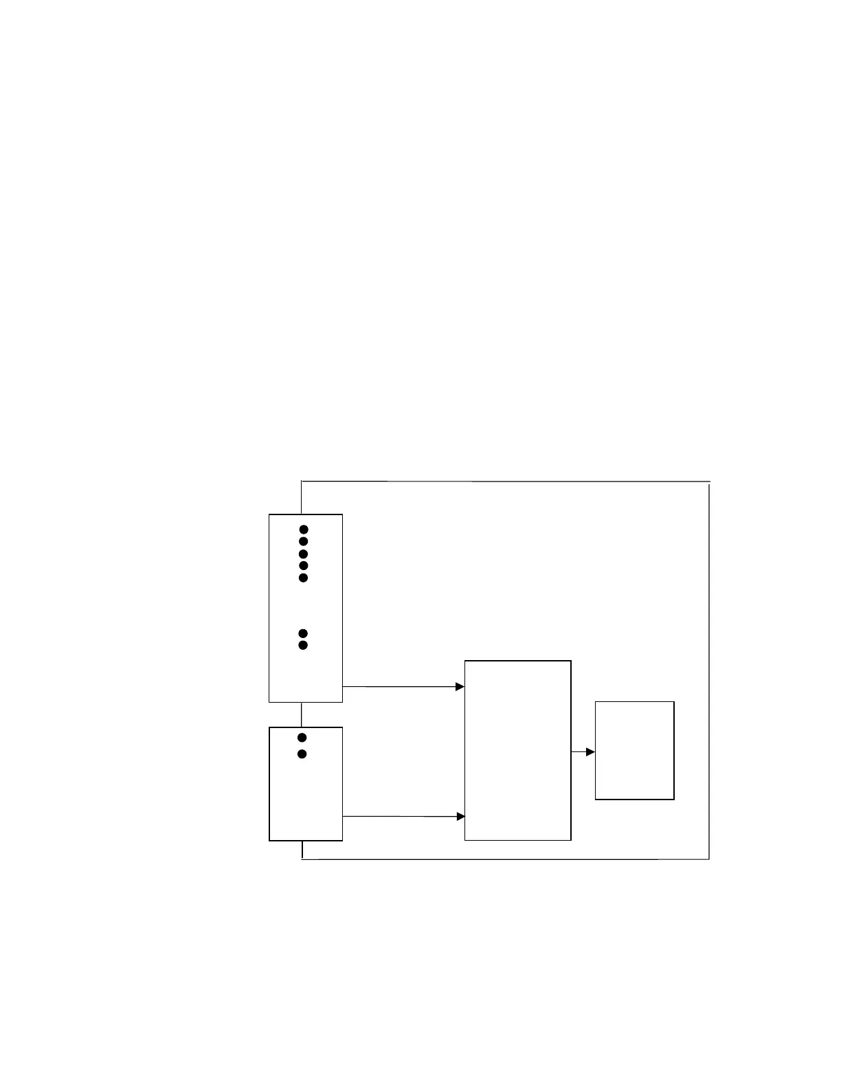
Pin 24 (+24/+5 Vdc)
Software Stop
Safety Interlock
Power
Interlock Loop
DB37
Optocoupler
Interlock Power
EMS/MOFF
Monitor Pins
Cut-off
J7
SCSI 68
I/O Board
Interlock Power
Motor
Pin 6 (-return)
Pin 3 (-return)
Circuit
Pin 24 (+24/+ 5Vdc)
Pin 20 (+24/+5 Vdc)
Pin 5 (-return)
Power
Circuit
Safety Interlock
Pin 67 (-return)
Pin 21 (- return)
Pin 23 (+ out)
optional