Pamux User’s Guide 51
WIRING ANALOG MODULES
This section lists all Pamux-compatible analog modules and provides wiring diagrams for each module
type.
Analog modules require up to four terminals per analog I/O channel. On the analog mounting rack, the
lower A and B terminals are typically used to distribute a 24 VDC shared-loop source for use with 4–20
mA modules.
Note that two types of analog modules are available: those that provide transformer isolation and those
that do not. Transformer-isolated modules include a “T” in the model number (e.g., AD3T, AD10T2) and
provide channel-to-channel isolation. For a list of all analog modules, as well as their current
requirements, see Appendix B.
IMPORTANT: Once connected to a rack, modules without transformer isolation create an electrical connection
from the negative field terminal (which is connected to the upper A terminal on the rack) to the
±15 VDC common. Hence, these modules do not offer channel-to-channel isolation. If you require
such isolation, select transformer-isolated modules only.
Voltage Input and Output Modules
Use Figure 2-33 on the following page, to wire all of the analog voltage input or output modules listed
in Table 2-19 except the AD15T. The diagram shows a voltage output module wired to channel 0, and
two voltage input modules wired to channels 2 and 4 on a PB16AH rack.
Note that for the AD9T and AD13T, there is no connection on the mounting rack (A and B terminals).
Instead, the connections are made directly to the module.
To wire the AD15T, refer to Figure 2-36 on page 54.
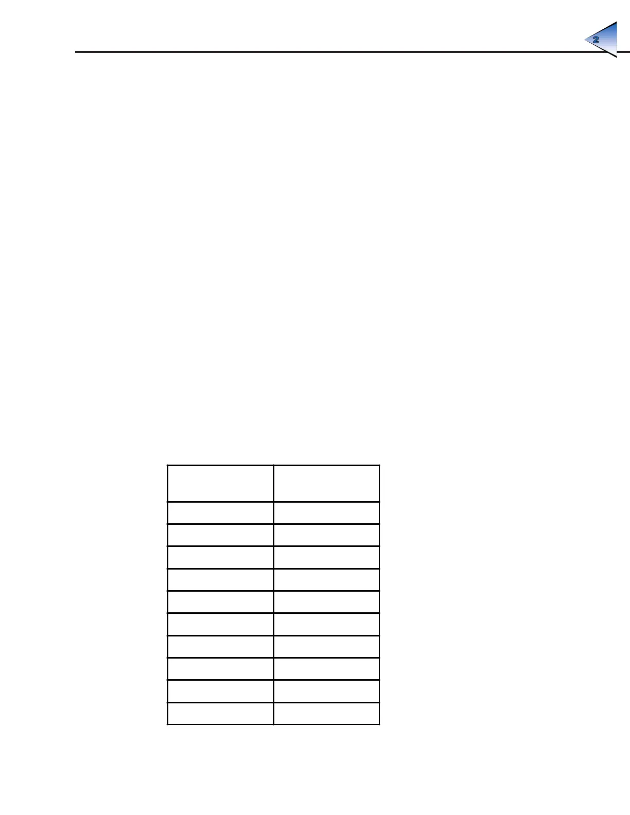
Table 2-19: Voltage Input and Output Modules
Voltage Input
Modules
Voltage Output
Modules
AD6 DA4
AD6T DA4T
AD6HS DA5
AD7 DA6
AD9T DA7
AD11 - - -
AD12 - - -
AD12T - - -
AD13T - - -
AD15T (AC only) - - -
SYSTEM SETUP