50 Pamux User’s Guide
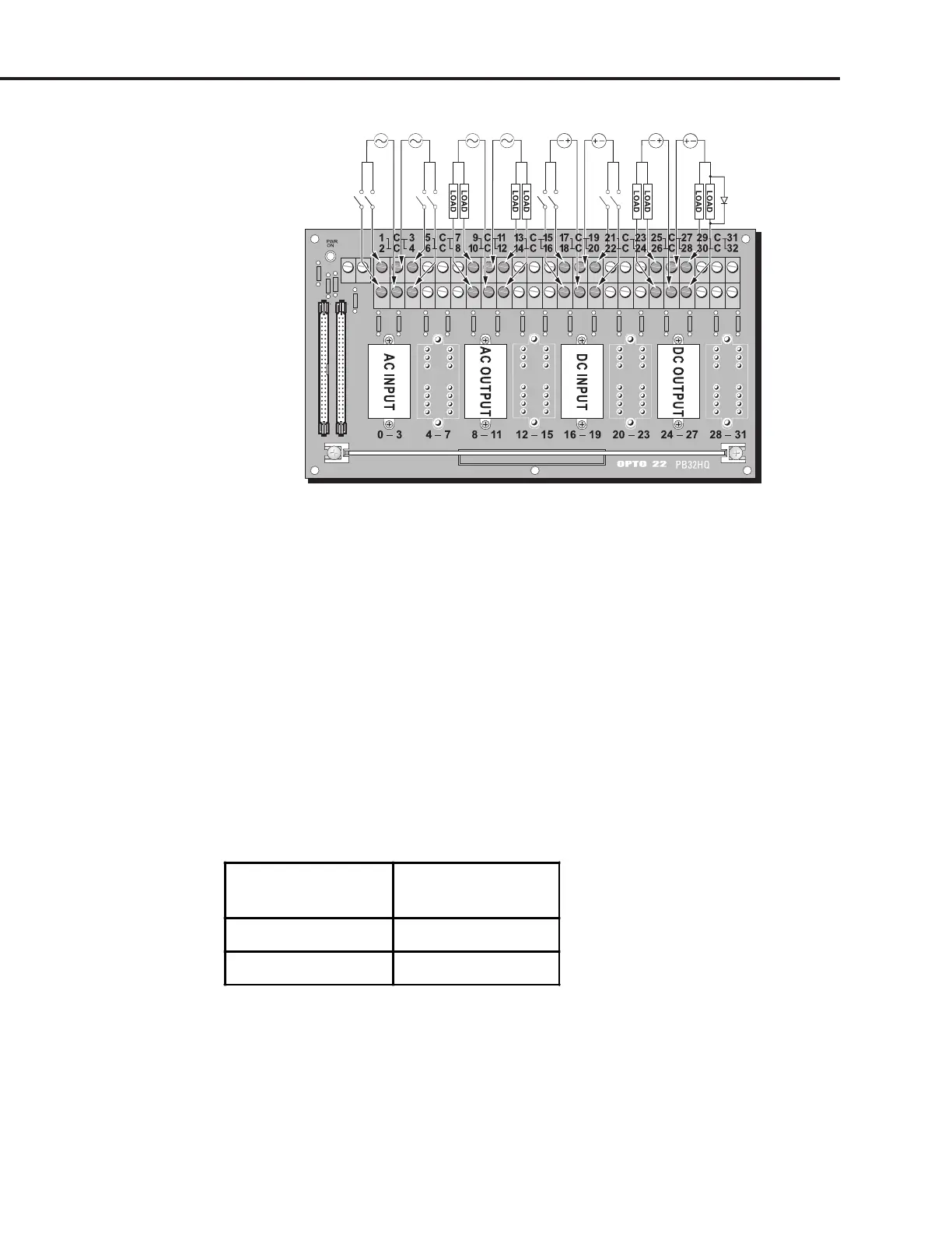
Figure 2-32: Wiring for Quad Pak Input and Output Modules
Output Modules
Use Figure 2-32 to wire the quad pak DC and AC output modules listed in Table 2-18. The diagram
shows a DC output module wired to channels 24–27 and an AC output module wired to channels
8–11 on a PB32HQ rack.
For the quad pak output modules listed in Table 2-18, the load may be wired to either line.
Note that the ‘C” terminal of DC output modules must be more positive when switching DC leads.
For DC output modules used with inductive loads, add a commutating diode (typically a 1N4005) to the
circuit as shown on the channel 27 connection to the PB32HQ rack.
Table 2-18: Quad Pak DC and AC Output Modules
DC Output
Modules
AC Output
Modules
ODC5Q OAC5Q
ODC5AQ
SYSTEM SETUP