Atmospheric Pre-aligner Manual
4000-0015 Rev 1
49
Pre-aligner I/Os (for Integrated Systems only)
This step tests the input/output connections for an integrated system.
Robot I/O ports are Port A and Port G. Pre-aligner connections are on
Port L and input is read from Port K. The two pre-aligner output bits and
the one input bit are described in the table.
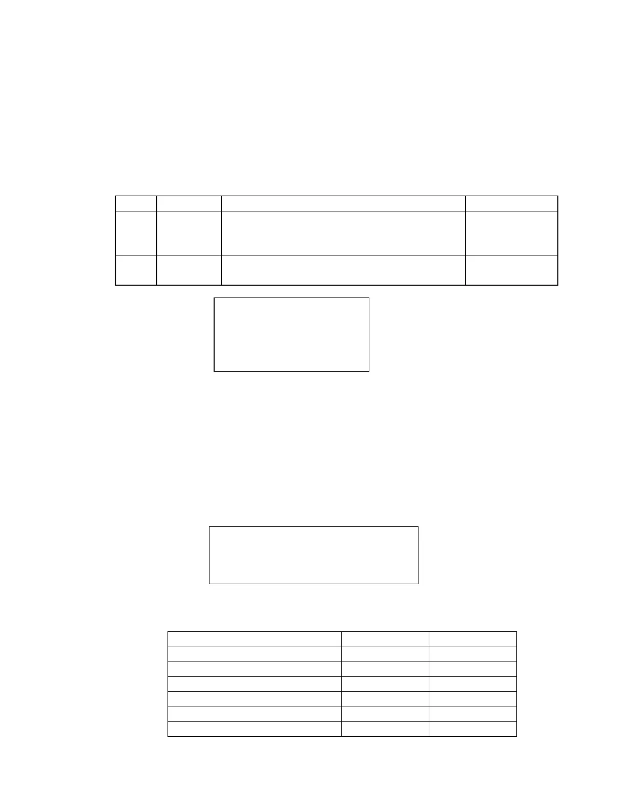
Port Port Type Bit Assignments I/O Number
L Output Bit 0 - Chuck vacuum valve. High to open.
Bit 1 - Pin vacuum valve. High to open.
Bits 2 through 7 - Not connected.
40
41
42 to 47
K Input Bit 0 - Chuck vacuum sensor. Low if activated.
Bits 1 through 7 - Not Connected.
40
41 to 47
Use the number keys, 0 and 1, to toggle the two output bits. The first two
bits should toggle, indicating that the robot connections are working. The
third and fourth bits should toggle to indicate the pre-aligner connections
are working. The remaining bits do not toggle.
CCD and Chuck Test
Use this test to verify that the CCDs and the wafer chuck are functioning
correctly.
CCD ANGLE E R N
ccccc aaaaa 0 0 n
R-Reset S-Servo
1, 2 or 3 CCD
The CCD number displayed on the first line is 1, 2, or 3, which indicates
the size of the wafer. The table below summarizes the CCD numbers for
various pre-aligners and wafer sizes.
Pre-aligner Wafer Size CCD #
PRE -300 or PRE-350 6 in (optional) 1
PRE -300 or PRE-350 8 in 2
PRE -300 or PRE-350 12 in 3
PRE -200 or PRE -050 3 or 4 in 1
PRE -200 or PRE -050 5 or 6 in 2
PRE -200 or PRE -050 8 in 3
BYTE #: 01234567
OUT 00111111
IN 11111111