Vacuum Robot Manual
4000-0315 Rev 1
7
Moving and Homing a Robot Axis
For the 400 series robots, the range of travel of each axis is physically
limited by mechanical hard stops. For the VAC514, the R and Z axes
have hard stops, but the theta axis has a full 360° rotation.
The negative and positive limit switches are located within the full travel
of the hard stops. The limit switches and home switches for each axis are
listed on page 2. In addition, you can set positive and negative software
limit switches. Software limits are logical limits that apply to
programmed motions.
A DC servo motor, a servo driver or amplifier, and a motion control board
control each robot axis. The servo motor is directly connected to an
optical encoder. The encoder and limit switch signals are input to the
Galil motion control board.
The Galil motion control board monitors the motor position by reading the
optical encoder and outputs a signal that controls the servo amplifier
current. The amplifier module amplifies the signal and sends the power to
the motor. The encoder on the motor provides feedback to the motion
control board to create the next output signal.
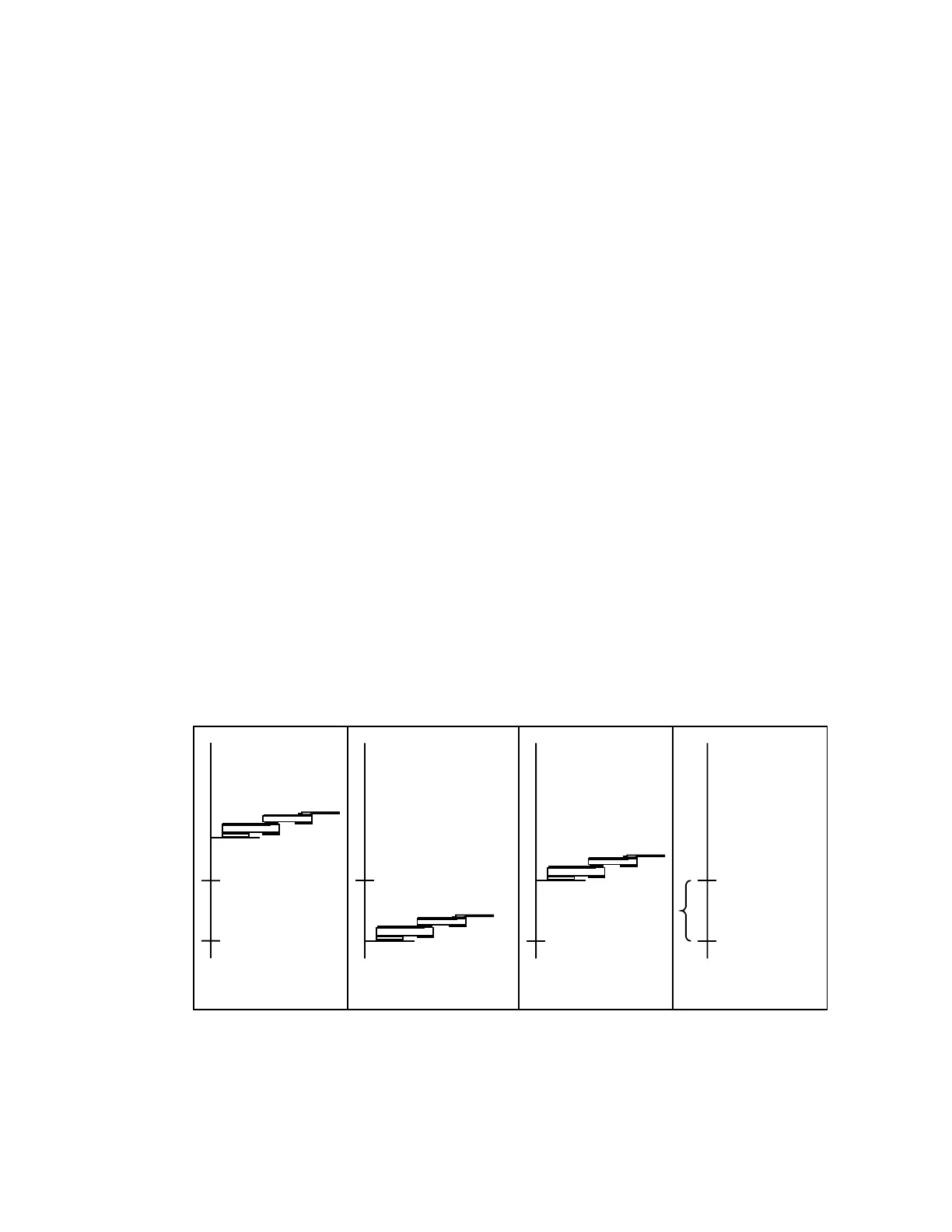
You can home the robot axis with a standard homing macro (HOM) or
with the HOME A command. During the robot homing sequence:
1. The robot axis moves towards the negative limit switch at the Home
speed defined in your Robot Parameter File (*.par file).
2. When the robot axis reaches that home switch, the home flag interrupts
the switch.
4. Distance to Index
Home Switch
2. Move to Home Switch
1. A starting position
Index Index
3. Move to Index
Home Switch
Index
Home Switch