52 Pamux User’s Guide
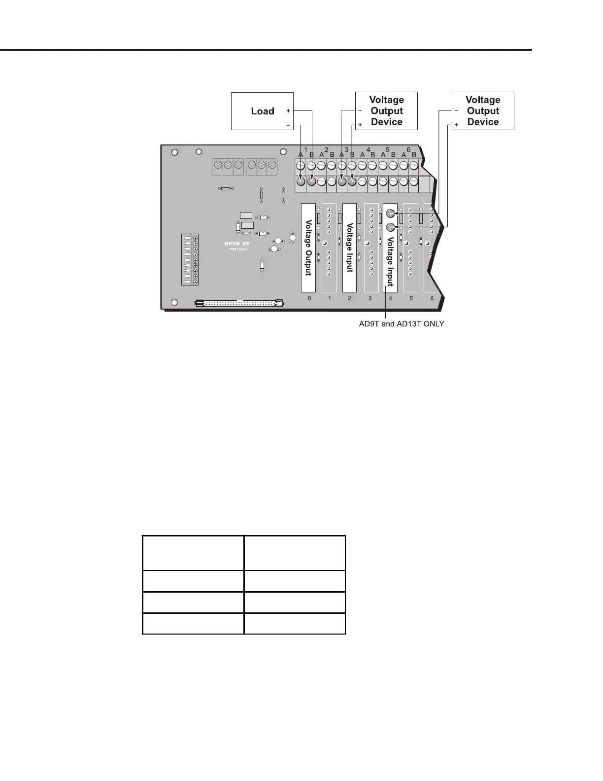
Figure 2-33: Wiring for Voltage Input and Output Modules
Milliamp Current Input and Output Modules
Use Figures 2-34 and 2-35 to wire the analog milliamp current input or output modules listed in
Table 2-20. The examples show wiring to a PB16AH rack on channels 0, 1, and 3.
Figure 2-34 shows wiring with individual power supplies. Figure 2-35 shows wiring with a shared loop
supply. In Figure 2-35, the wiring takes advantage of the fact that all lower A terminals on the mounting
rack are tied together. These provide a convenient tie point for shared loop source return. Connect one
lower A terminal to the shared loop source “–,” then jumper each upper A to its respective lower A for
each current module.
The current loop for an input or output current device must be powered by a user’s external supply.
Table 2-20: Milliamp Current Input and Output
Milliamp Current
Input Modules
Milliamp Current
Output Modules
AD2T DA3
AD3 DA3T
AD3T DA8
SYSTEM SETUP