Pamux User’s Guide 23
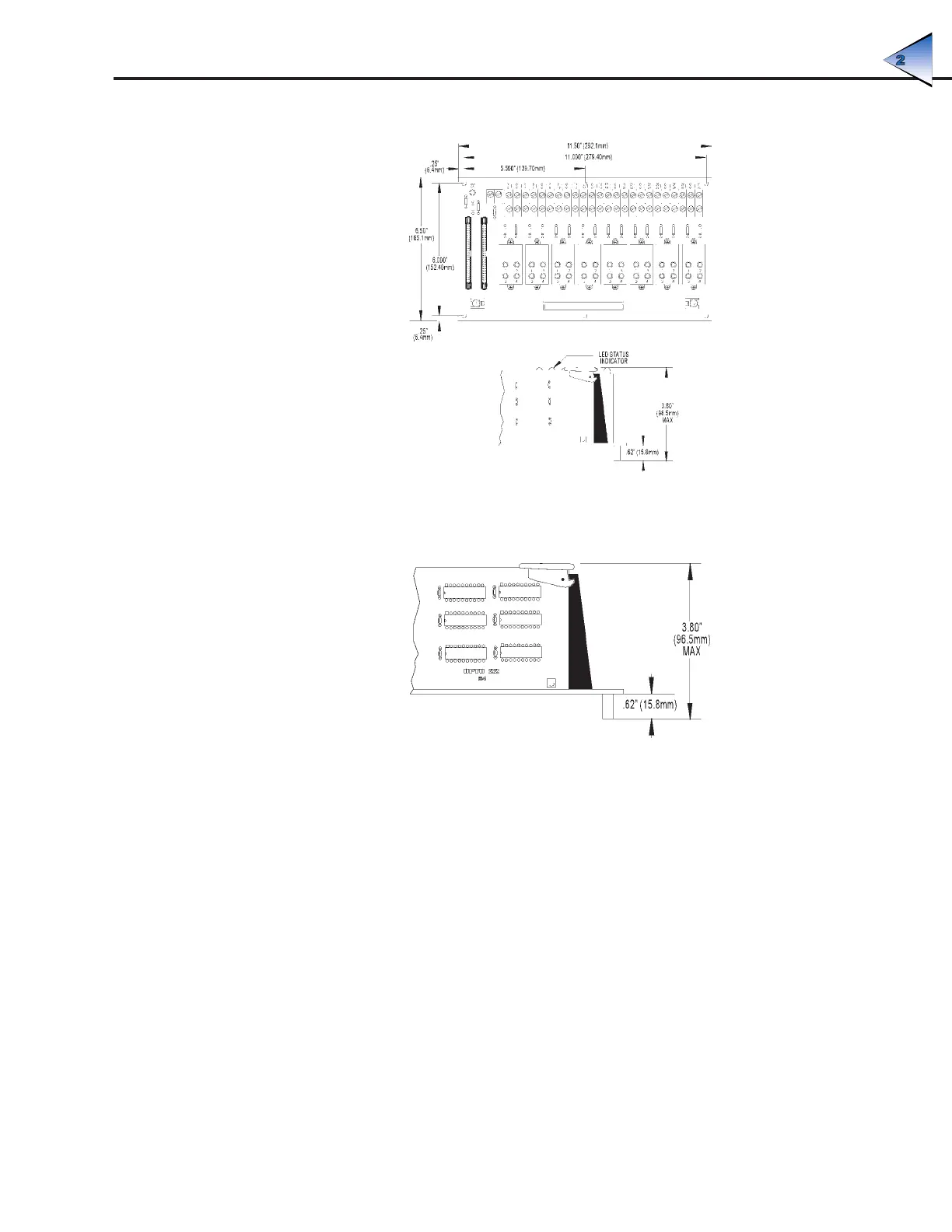
Figure 2-7: Mounting Dimensions of the PB32HQ
Figure 2-8 shows the vertical dimensions of the B4 mounted on either rack.
Figure 2-8: Vertical Dimensions of the B4 Mounted on a Rack
SETTING B4 JUMPERS
The B4 includes eight jumpers. Jumpers 1 through 4 set the address, jumpers 5 and 6 set the watchdog
functionality, and jumpers 7 and 8 determine the behavior of the reset line.
Jumpers 1–4 (Address)
These jumpers configure the base address of the B4. Since the brain board controls 32 points of I/O,
while the Pamux data bus is only eight bits wide, the B4 must be accessed as four consecutive banks
of eight I/O channels each. Each bank has its own address.
The four banks on the B4 have contiguous addresses. The bank 0 address is the base address of the
B4; the bank 1 address is the base address plus one; the bank 2 address is the base address plus
two; and the bank 3 address is the base address plus three. Hence, only the base address needs to
be configured. Refer to Table 2-1 to determine how to set this base address.
Note that each Pamux station on a bus must have a unique address.
SYSTEM SETUP