Pamux User’s Guide 43
TERMINATING A B6 STATION
For stations on a Pamux bus to operate correctly, both ends of the bus must be terminated. The
host computer and the last Pamux station on the bus are the only devices that should be terminated.
Note that if you are using an Opto 22 Pamux adapter card, the host computer is automatically
terminated, since termination resistors are built into the card.
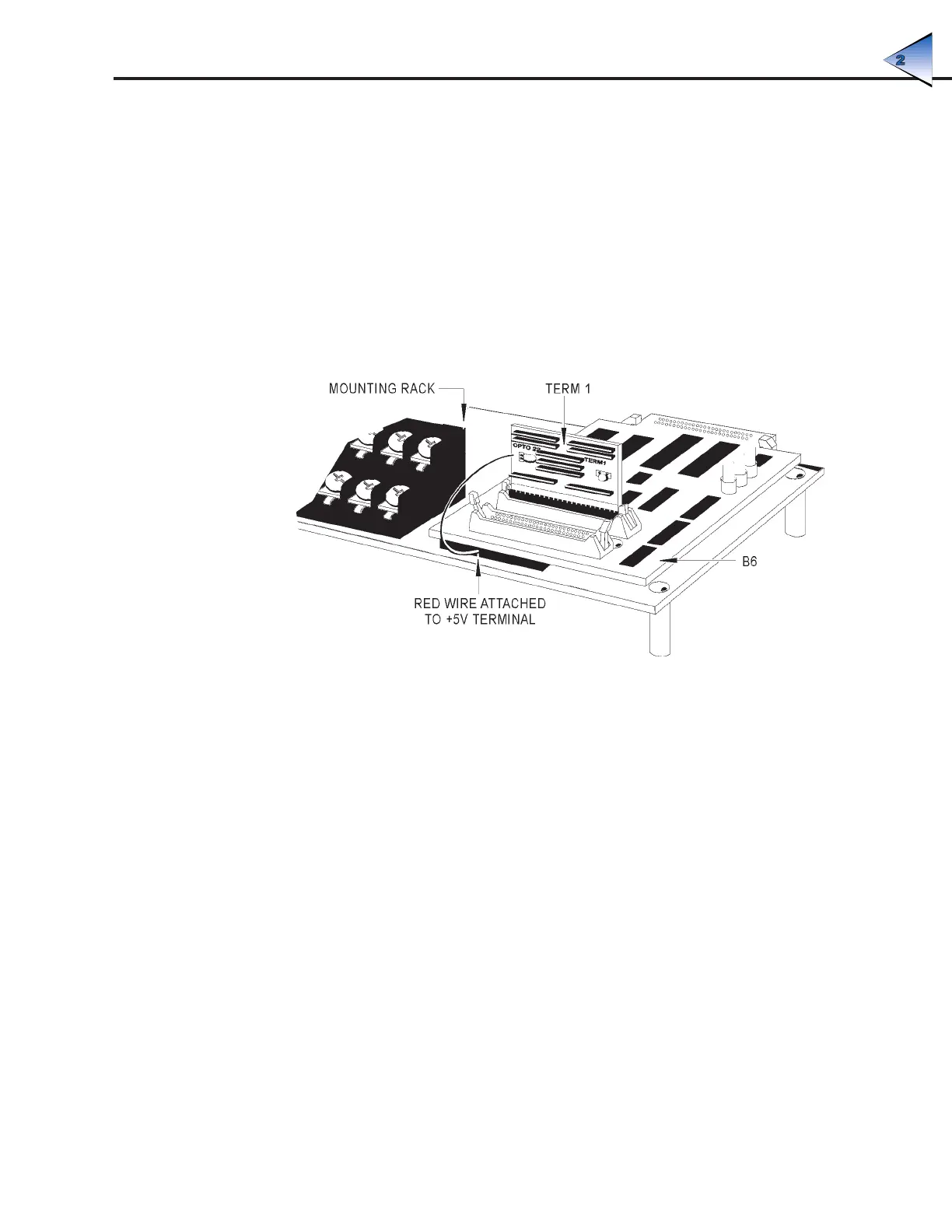
To terminate a B6 station, plug a Pamux bus terminator board (TERM1 or TERM2) into either
connector on the brain board. When the terminator board is installed correctly, its component side
faces away from the brain board components and its red wire connects to the +5V terminal on the
rack.
Figure 2-30 illustrates the proper installation of the terminator board.
Figure 2-30: Terminator Board Installed on a B6-Compatible Mounting Rack
B6 LED INDICATORS
The B6 brain board includes the following LEDs:
• Address — This LED is on whenever the brain board is addressed (read from or written to)
on the Pamux bus. It is off otherwise. For each operation the LED stays on for about 250
msec, so if the bus is very active the LED may appear constantly on.
• Access — This LED is on whenever access has been granted to the dual-port RAM. It
remains on until access is released. (See Chapter 4 for details on getting and releasing
access.)
• Power — This LED is on whenever power is connected to the board. It is off otherwise.
SYSTEM SETUP