Pamux User’s Guide 115
The following example shows how to configure and write an output on a Pamux B6 brain board, using
the DOS Debug utility. The Debug utility uses “o” to command an output to a port, and “i” to read data
at a port. The same port reading and writing structure is used in a high-level language to perform the
same operation. To run Debug, type ‘debug’ at the DOS prompt.
For an AC28 configured at port 140h, and a B6 at Pamux address 20:
>Data Register = AC28 Port + Address Offset = 140h + 20 = 160h
>Control Register = AC28 Port + Address Offset + 1 = 140 + 20 + 1 = 161h”
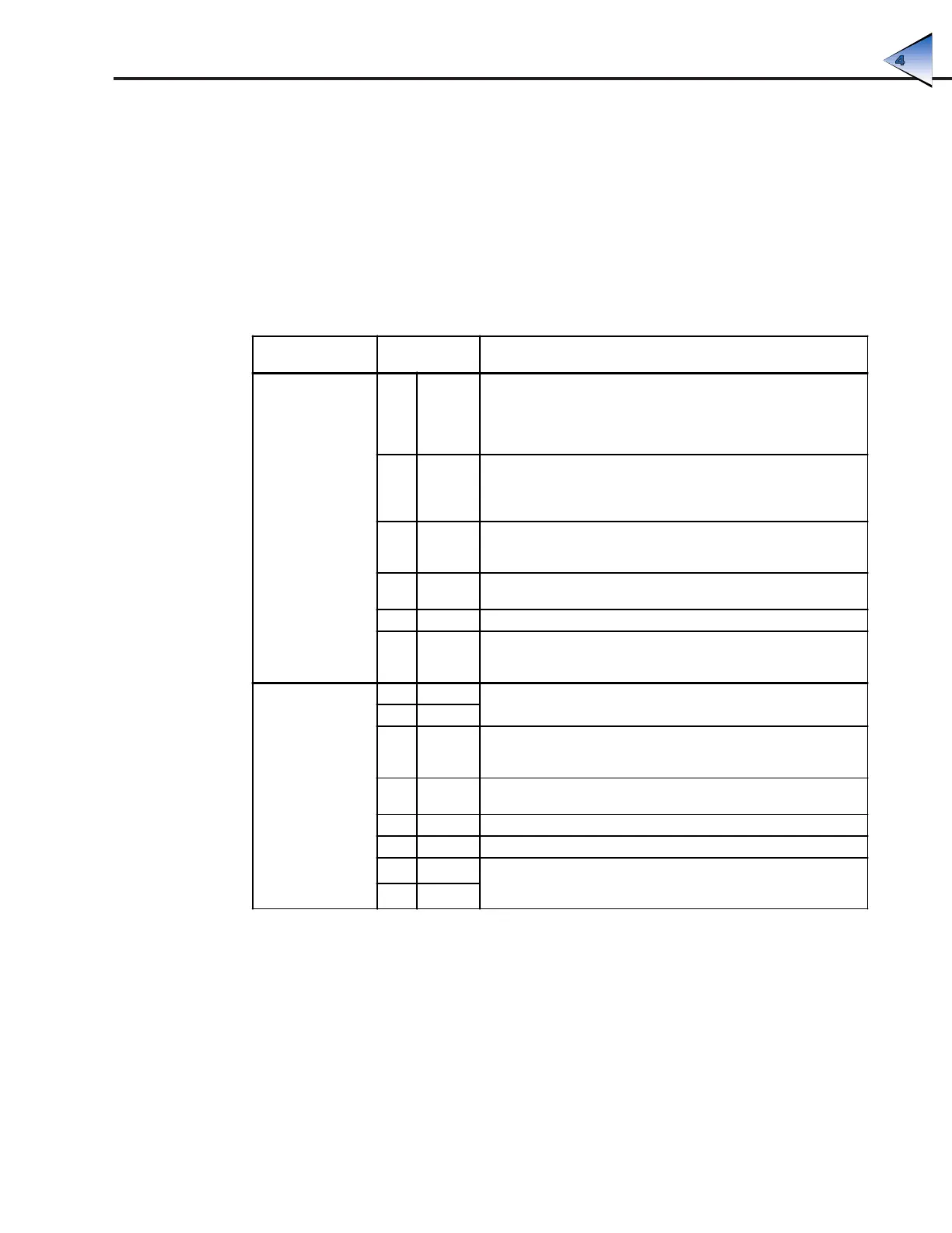
Table 4-3: Instructions — Pamux Access With DOS Debug
Type the
Following
Reason
CONFIGURATION
1. o161 82
Request access to B6 dual-port RAM by requesting semaphore
(signaling) register. "Semaphore" comes from the maritime flag-
waving method of communication between ships — this register
serves as the flag that is "waved" to get the attention of the
B6 brain board.
2. i160 00
Test for access. A 00 is actually a "no access" code, but the act of
testing for access will cause access to be granted. If this step is
repeated, the board will return C0, indicating access. This second
test is not required, however.
3. o161 7E
Writing 7E to control register gains access to lower configuration byte
per Table 4-2; any data written to the data register will now be placed
in the lower configuration byte.
4. o160 FF
Writing FF to the data register configures the lower byte as all outputs
(FFh = 11111111b).
5. o161 82 Request the semaphore register again.
6. o106 FF
Writing any data to the semaphore register after access has been
granted releases access; FF is convenient. The board is now
configured.
READ
7. o161 82
Now that the board is configured (only needs to be done on power-
up), get access to write output channels.
8. i160 00
9. o161 00
Writing 00 to the control register sets the B6 to receive the low data
byte for output channel 0per Table 4-2; remember, a 12-bit number
must be expressed as two bytes.
10. o160 FF
Write data for channel 0 low byte. FF is the less significant byte of
0FFFh, or 4095 in decimal. This is equivalent to a full-scale output.
11. o161 01 Set up to write the upper byte of data to output channel 0.
12. o160 0F Write high data byte. 0Fh is the more significant byte of 0FFFh.
13. o161 82
Release access to board. As soon as data has been written to the
semaphore register, the board is released and any output module on
channel 0 of this B6 should go to full-scale.
14. o160 FF
PROGRAMING WITHOUT THE PAMUX DRIVER