G4PB8H MOUNTING RACK
G4 Digital I/O Family Data Book 9
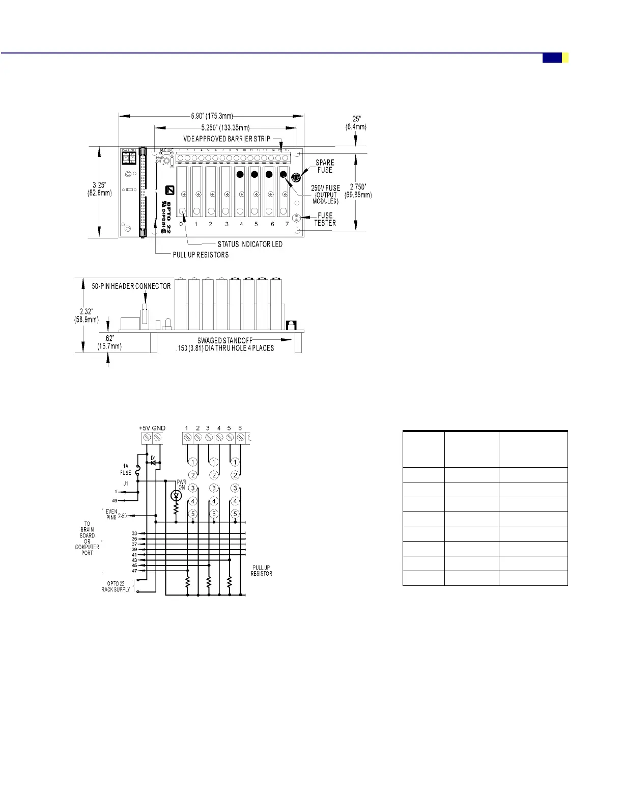
Dimensions—G4PB8H
Connections—G4PB8H
Notes:
1. Even pins on control
connector are connected by
etch to common.
2. +VCC and return connected to
terminals marked +5V and
GND.
3. At each module position on
the field terminal strip, the
lower number is always
connected to pin 1 of the I/O
module.
4. Use only 5 VDC logic modules
when using the mounting rack
with a brain board.
0RGXOH
3RVLWLRQ
&RQWURO
õ+HDGHU
&RQQHFWRUô
)LHOG
õ7HUPLQDO 6WULS ô
í éæ ì DQG ë
ì éè ê DQG é
ë éê è DQG ç
ê éì æ DQG å
éêääDQGìí
è êæ ìì DQG ìë
ç êè ìê DQG ìé
æ êê ìè DQG ìç