D950 Digital Mixing System
6-16 System Administration SW V3.3 Date printed: 05.12.03
6.7 Signaling & Monitoring Setup
6.7.1 System Overview
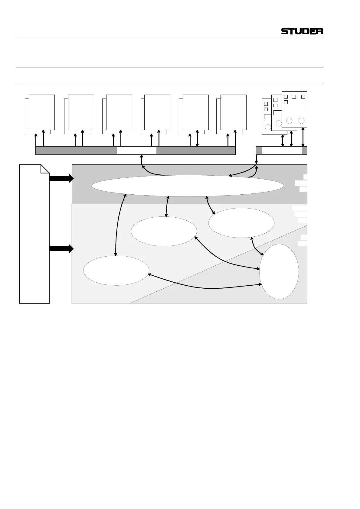
Block diagram of the monitoring (signaling and talkback) system
Hardware components: The user interface of the monitoring system comprises a series of dedi-
cated control panels:
1.950.890 Input selector panel with 20 keys;
1.950.855 Input selector panel with 10 keys and alpha-numeric displays;
1.950.860 CR monitor panel (stereo);
1.950.870 Studio monitor panel (stereo);
1.950.880 Headphones/Talkback/PFL-Solo panel;
1.950.720 Surround panel.
The panels contain controls (keys, potentiometers) and display elements
(LEDs, alpha-numeric displays). The control panels, together with the sig-
naling input cards, are capable of producing input to the control system.
The routing and switching of the audio signals is done by a number of
audio cards:
• Analog input selector;
• Insert router;
• Monitor group selector;
• Dual headphones card;
• Talkback router.
VMC
CONTROL
SIGNALING
I/O
CONFIGURATION
ANALOG
SOURCE
SELECTOR
INSERT
ROUTER
SERIAL INTERFACE CONTROL
TB
ROUTER
MONITORING
FUNCTIONS
SIGNALING
FUNCTIONS
TALKBACK
FUNCTIONS
CONTROL
PANELS
CONTROL PC
DUAL
HEAD-
PHONES
CARD
MONITOR
GROUP
SELECTOR
HW
INTERFACE
LAYER
VMC
LAYER
MON/SIG/TB
CONTROL
LAYER
serial bus (RS485) serial bus (RS485)