D950/Vista Digital Mixing System
Date printed: 05.08.03 SW V3.3 GC Operation 4-23
4.4.2.2 How to Deal with the Analog Interfacing?
“Where are the analog interfaces coming in?”, you might be asking. We
still need some analog sound. Here is how we achieve that task:
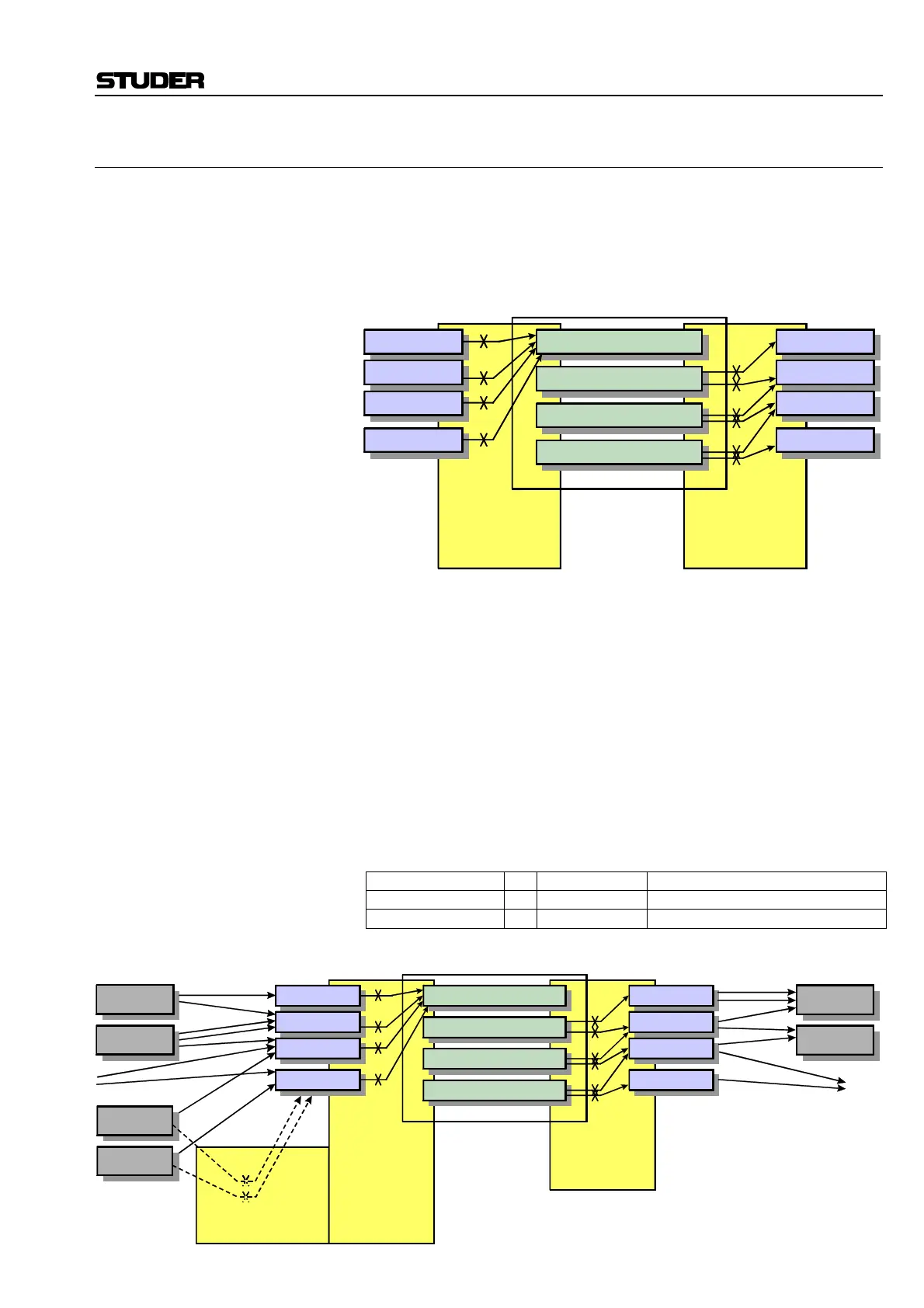
The D950/Vista Patch and DSP systems only know about digital interfac-
ing, as can be seen from the following simplified block diagram:
To accommodate analog sources, we need to make a distinction between
• Remotely controllable devices (D19m/D21m mic pre-amps), and
• Non-controllable devices (D19m/D21m A/D and D/A converters).
The mic pre-amps have to be connected to the system using General Patch
connections, in order to establish the correct remote control and audio in-
puts. In addition, they are also hardwired to digital inputs (AES/EBU or
MADI).
All other currently available analog interfaces are only hardwired to their
digital counterpart sources.
For this reason, all microphone/line sources coming from D19m/D21m
mic pre-amps need to be patched twice (where one of these patches re-
mains the same as long as the wiring of the analog pre-amps to the digital
input is not changed):
Source to Target Reason
D19m Mic/Line Pre
to
Ext Target Prepare the remote control link, and
Digital Input
to
e.g. Channel In1 Establish the connection & control link
Input Channels
Group Channels
AUX Channels
Master Channels
AES/EBU
MADI
AES/EBU
MADI
Input Patch
Crosspoints
AES/EBU
MADI
AES/EBU
MADI
Output Patch
Crosspoints
Sources
Targets
Targets
Sources
Input Channels
Group Channels
AUX Channels
Master Channels
AES/EBU
MADI
AES/EBU
MADI
Digital Inputs
DSP Channels Digital Outputs
Input Patch
Crosspoints
AES/EBU
MADI
AES/EBU
MADI
Output Patch
Crosspoints
Sources
Targets
Targets
Sources
Ext. MicPre
& Ext. Target
Crosspoints
Connections
Analog Inputs
Connections
Outputs
External,
Remote-Controlled
MicPre Sources
D21m A/D
D19m MicPre
D21m MicPre
D19m A/D D19m D/A
D21m D/A