D950 Digital Mixing System
Date printed: 03.09.03 SW V3.3 Desk Operation 3-9
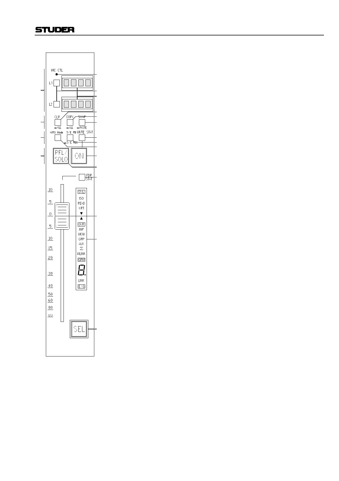
[7] AUTO Mode
This key toggles the AutoTouch Dynamic Automation mode between ISO,
READ and WRT for the entire channel.
[8] S/E PB / ••S/E REC (switches and encoders playback/record)
A double-click of this key engages the Dynamic Automation active REC-
ORD status for the channel’s switches and rotary encoders.
A subsequent press returns the switches and encoders back to PLAY-
BACK status.
[9] MUTE STAT
This key toggles the status of the Mute Automation between RECORD and
PLAYBACK, and indicates that the channel ON key is in REC status.
[10] PFL/SOLO
This key engages the PFL or SOLO for the channel. The particular PFL or
SOLO mode is determined by a global selection in the center section.
[11] ON
This key provides ON/OFF (mute) control for the currently active channel.
[12] FDR STAT (fader status)
This key allows toggling automation status RECORD and PLAYBACK
for the fader only, and also indicates that the fader is in REC status.
[13] Fader
This 104 mm touch-sensitive, motorized fader serves as the primary level
control for the channel’s audio path.
[14] SEL
The channel selection (CH SEL) key has two main purposes:
• Access of the central audio and control facilities (CAU, ACU, etc.),
• Softkey for channel parameter control (SOLO SAFE, CH SWAP, etc.).
In addition, this key is used for other functions including control group,
strip lock, and joystick assignments and so on.
[15] Fader LED Indicators:
OVL = indicates real-time overloads occurring within the channel.
ISO/READ/WRT = indicates the current Dynamic Automation mode.
i, z = indicate offset – i.e., greater or less than – between the current
fader position and the value stored by the Dynamic Automation.
OVR = indicates an out-of-range condition for the channel fader.
INP, MON, GRP, AUX, Σ = indicates channel types: input, tape monitor,
group, auxiliary, or master.
MLINK = indicates that this particular Channel Strip is a Link Master
(control group master).
Digit Display = indicates the Link number (control group number).
LINK = indicates the Channel Strip is a Link member (control group
member).
E/G = indicates real-time Expander/Gate activity.
[A]
[B]
[D]
[C]
[1]
[2]
[3]
[5]
[4]
[6]
[9]
[8]
[7]
[11]
[10]
[12]
[15]
[13]
[14]