Chapter 6 – Additive Control
Firmware Version 3/4.31.37
Choose the port that will serve as the additive injection (output) signal for the selected
additive. Possible choices are 0-3 (0-1 on SMP). This port choice also automatically
chooses a port to serve as either the additive meter input or the additive feedback
signal.
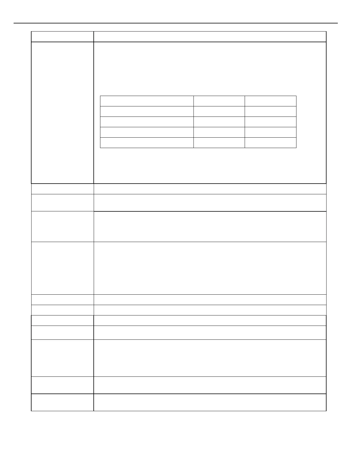
The following list shows which additive meter input/injector feedback input corresponds
to what additive port.
Additive Port Additive Meter/Injector Feedback Input
Injector #3 (Excluding SMP)
Injector #4 (Excluding SMP)
For example, if Additive Port #0 is chosen, the additive solenoid will be energized by the
port 0 output and the additive meter input signal will be expected at port 7. If a
calibrated cylinder is used with no additive meter, a feedback signal can be sent to port
7 to verify that the piston has completed the injection cycle.
Enables select additive parameters for this additive to be under W&M control.
Enable this parameter if the additive block valve is upstream of the injector. When
enabled, the additive block valve will be opened during additive calibration.
Controls how additive recipe should be calculated, apart from the preset Delivery Type.
If set to GROSS, the target volume will be based off of the gross volume delivered. If set
to NET, the target volume will be based off of the net volume delivered. If set to MASS,
the target volume will be based off of the mass amount delivered.
Choose the type of additive control to use, which is one of:
SolnMtr – Solenoid with meter
PstnNFB – Piston with normal feedback
PstnIFC – Piston with inverted feedback
Pstn – Piston with no feedback
AnlgMtr – Analog valve with meter with PID control
Proportional gain for PID loop (only applies to analog valve additive type)
Integral gain for PID loop (only applies to analog valve additive type)
Derivative term for PID loop (only applies to analog valve additive type)
This parameter will set the loop current when the additive control is IDLE. This is only
related to a 4-20mA additive type.
There are 3 Additive Modes:
StrBtch: Injection of the additive starts at the start of the batch.
StrHigh: Injection of the additive starts when the preset goes to High Flow.
StrVol: Injection of the additive starts when the start volume or restart volume is
exceeded.
This is the start volume when the additive will try to injection again. This parameter is
only used when Additive Mode StrVol is selected.
This is the restart volume when the additive will try to injection again. This parameter is
only used when Additive Mode StrVol is selected.